Sliding window with automatic dust removal function

A technology of automatic dust removal and sliding windows, which is applied in the field of windows, can solve the problems of limited ventilation area, harm to health, difficulty in sliding windows, etc., and achieve the effect of reducing troubles and delaying dust discharge

Active Publication Date: 2018-11-30
LIXIN FUYA GAUZE CO LTD
View PDF4 Cites 10 Cited by
  • Summary
  • Abstract
  • Description
  • Claims
  • Application Information

AI Technical Summary

Problems solved by technology

The window sash is in a good stress state and is not easy to be damaged, but the ventilation area is limited to a certain extent
[0003] When the existing sliding windows are in use, because the sliding grooves are set open, especially as the smog weather becomes more and more serious, more dust will accumulate in the sliding grooves, and people often raise the dust when opening and closing the windows. , endanger people's health, not only that, after a long time of use, the dust will often block the sliding groove, resulting in the difficulty of pushing and pulling the window

Method used


Image

  • Sliding window with automatic dust removal function
  • Sliding window with automatic dust removal function
  • Sliding window with automatic dust removal function

Examples


Embodiment 1

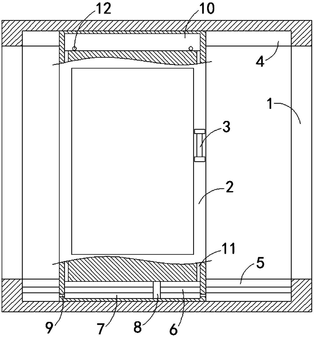
[0018] Such as figure 1 As shown, a sliding window with automatic dust removal function includes a window frame 1 and a form 2. It should be noted that the lower end of the form 2 is fixedly connected with a sealing top (not shown in the figure), and the sealing top ensures that the window 2. At the same time of airtightness, in the process of moving with the window 2, it will also sweep from the bottom surface of the groove to sweep up the dust adsorbed on the bottom surface of the second sliding groove 5, so that the dust in the second sliding groove 5 is easier to clean. Sucked away by the air flow, the side wall of the form 2 is fixedly connected with a handle 3, the inner top surface and the inner bottom surface of the window frame 1 are respectively provided with a first slide groove 4 and a second slide groove 5, and the upper and lower sides of the form 2 The ends are respectively located in the first sliding groove 4 and the second sliding groove 5, and the second sli...

Embodiment 2

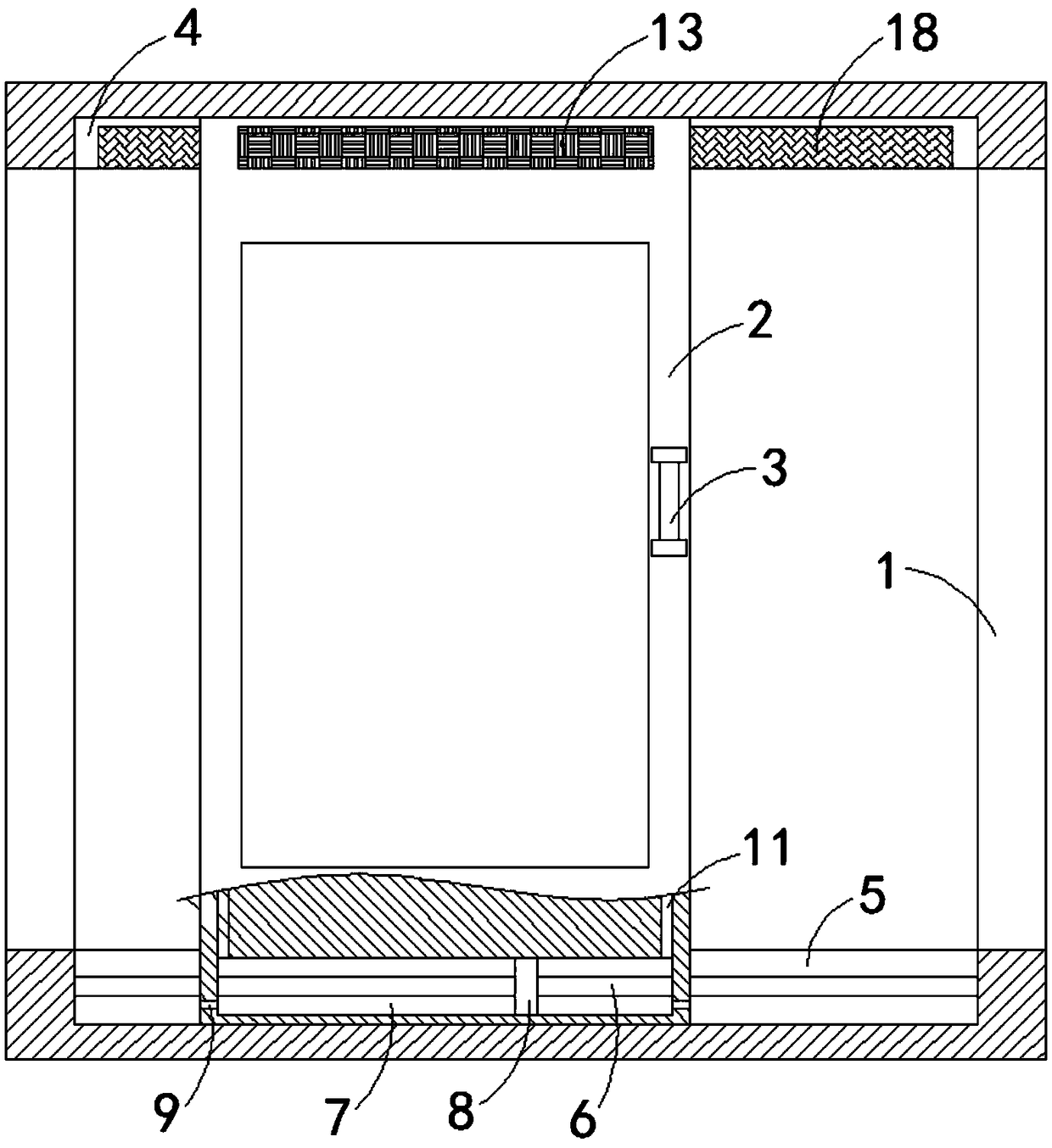
[0022] Such as Figure 2-4 As shown, the difference between this embodiment and Embodiment 1 is that: the front and rear side walls of the exhaust chamber 10 are respectively provided with a first opening and a second opening, the first opening is fixedly connected with a glass mesh plate 13, the second A rubber net plate 14 is fixedly connected in the opening, a first induction plate 15 and a second induction plate 16 are respectively fixedly connected on the opposite side walls of the glass net plate 13 and the rubber net plate 14, and the front and rear inner walls of the first slide groove 4 are respectively A silk layer 17 and a fur layer 18 are fixedly connected, and the exhaust port 12 is arranged obliquely downward from the inside to the outside. The angle of inclination is the same.

[0023] In this embodiment, when the window 2 moves, friction will be generated between the glass net plate 13 and the silk layer 17, the rubber net plate 14 and the fur layer 18. Accord...


PUM


Abstract

The invention belongs to the field of a window, and particularly relates to a sliding window with an automatic dust removal function. The sliding window comprises a window frame and a window body, wherein a handle is fixedly connected onto the side wall of the window body; a first sliding groove and a second sliding groove are respectively formed in the inner top surface and the inner bottom surface of the window frame; the upper end lower ends of the window body are respectively positioned in the first sliding groove and the second sliding groove; a sliding rod in horizontal arrangement is fixedly connected in the second sliding groove; the lower part of the window body is provided with a gas suction cavity; the sliding rod is arranged in a way of penetrating through the air suction cavity; the sliding rod and the air suction cavity are glidingly connected in a sealed way; a piston block is fixedly sleeved and connected onto the sliding rod; the piston block and the air suction cavityare glidingly connected in a sealed way; an air suction opening communicated with the outside is formed in each of the left and right side walls of the air suction cavity; a first one-way valve is fixedly connected in the air suction opening; an exhaust cavity is formed in the upper part of the window body. In the use process, the dust in the sliding groove can be treated; the influence on the normal use of the sliding window due to the long-time accumulation of the dust can be avoided.

Description

technical field [0001] The invention belongs to the field of windows, in particular to a sliding window with an automatic dust removal function. Background technique [0002] Sliding windows are divided into two types: left and right, and up and down. Sliding windows have the advantages of not occupying indoor space, beautiful appearance, economical price and good airtightness. It adopts high-grade slide rails, which can be opened flexibly with a slight push. Coupled with large pieces of glass, it not only increases indoor lighting, but also improves the overall shape of the building. The window sash is in a good stress state and is not easy to be damaged, but the ventilation area is limited to a certain extent. [0003] When the existing sliding windows are in use, because the sliding grooves are set open, especially as the smog weather becomes more and more serious, more dust will accumulate in the sliding grooves, and people often raise the dust when opening and closin...

Claims


Application Information

Patent Timeline
Patent Type & Authority Applications(China)
IPC IPC(8): E06B3/46E06B7/22E06B7/28A47L1/02
CPCA47L1/02E06B3/4636E06B7/22E06B7/28
Inventor 邵凌云
Owner LIXIN FUYA GAUZE CO LTD
Why Eureka
Try Eureka