Autonomous escape system and escape method for high-rise building

A high-rise building and escape system technology, applied in the field of fire rescue, can solve the problems of dense personnel, height restrictions, and surrounding environment restrictions, and achieve the effects of reducing secondary injuries, ensuring stability, and reducing fear

Active Publication Date: 2019-03-12
窦鹏
View PDF6 Cites 4 Cited by
  • Summary
  • Abstract
  • Description
  • Claims
  • Application Information

AI Technical Summary

Problems solved by technology

[0002] At present, the structure of high-rise buildings is becoming more and more complex, and the population is becoming more and more dense. Once a fire occurs, it is difficult to control
Due to the chimney effect of stairs, shafts and elevators in case of fire, the normal use cannot be guaranteed, which brings great difficulty to the emergency escape of people in high buildings
Existing fire-fighting equipment has a single variety. The equipment used for climbing and rescue is mainly fire-fighting aerial ladder vehicles. Its maximum lifting and rescue capacity is currently about 100 meters. Fighting and Rescue Escapes
[0003] Existing escape devices for high-rise buildings mainly include slow descent, escape elevators, escape slides, emergency parachutes, escape air cushions, etc., but the existing escape devices have the following problems: 1. There are height restrictions and cannot be used for high-rise buildings
2. The descending speed is too fast, and it is easy to lose control and cause personal injury
3. Only for one person, limited by the surrounding environment
4. Rely on electric energy and cannot be used when there is no electricity

Method used


Image

  • Autonomous escape system and escape method for high-rise building
  • Autonomous escape system and escape method for high-rise building
  • Autonomous escape system and escape method for high-rise building

Examples


Embodiment Construction

[0034] In order to make the objectives, technical solutions and advantages of the present invention clearer, the present invention will be further described in detail below with reference to the accompanying drawings and embodiments.

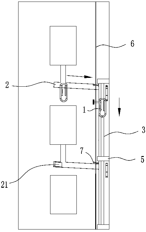
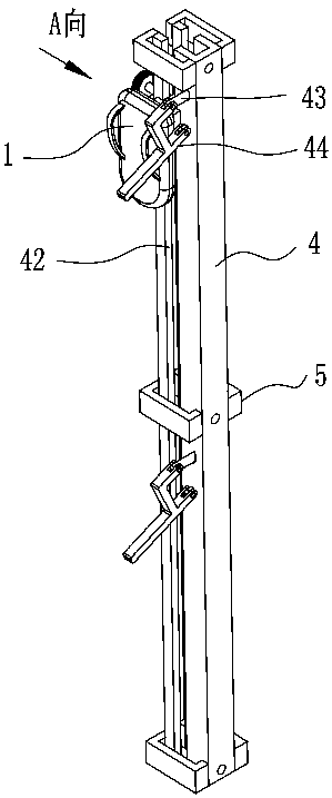
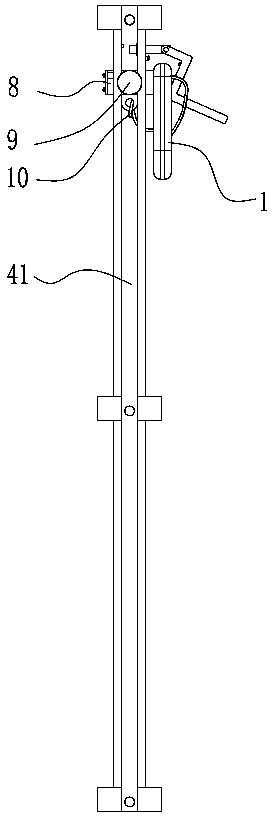
[0035] like Figure 1 to Figure 3 As shown, the present invention discloses an autonomous escape system for a high-rise building, comprising an escape backpack 1, a horizontal grooved track 2, a vertical grooved track 3 and a water spray assembly arranged on the high-rise building. The transverse trough track 2 is arranged on the outside of the wall of each floor of the building and connected to the window sill of each unit. The transverse grooved track 2 is provided with a transverse sliding block 21 with hook holes. The ends of the transverse grooved rails 2 are connected with the vertical grooved rails 3 .

[0036] The vertical trough track 3 extends from the junction of the top floor of the building and the horizontal trough track 2 to the...


PUM


Abstract

The invention discloses an autonomous escape system for a high-rise building. The autonomous escape system for the high-rise building comprises an escape knapsack, a horizontal slot type rail and a vertical slot type rail, wherein the horizontal slot type rail and the vertical slot type rail are arranged on the high-rise building; the end part of the horizontal slot type rail is connected with thevertical slot type rail; the vertical slot type rail extends to a building bottom from the connected part of the topmost layer of a building and the horizontal slot type rail, and comprises multiplesections of vertical single rails; each two sections of vertical single rails are connected through a fixed frame; a one-way inserting type assembly, a control bolt and at least two groups of spring fasteners are fixed onto the escape knapsack; a sliding main slot and slot rails arranged on two sides of the sliding main slot are arranged on each vertical single rail; the one-way inserting type assembly is inserted into the slot rails; and the control bolt is perpendicular to the sliding main slots so as to be screwed into the middle part of the one-way inserting type assembly and is abutted against the inner walls of the sliding main slots. The invention further discloses an escape method of the system. The autonomous escape system for the high-rise building provided by the invention is not limited by the building height, and is simple to install, low in cost, dispense with electric energy, and capable of being used by multiple persons.

Description

technical field [0001] The invention relates to the technical field of fire rescue, in particular to a high-rise building escape system and an escape method. Background technique [0002] At present, the structure of high-rise buildings is becoming more and more complex, and the people are more and more dense, and it is difficult to control once a fire occurs. Due to the chimney effect of stairs and shafts, and the normal application of elevators cannot be guaranteed in the event of fire, it brings great difficulty to the emergency escape of high-rise people. The existing firefighting equipment has a single variety. The equipment used for climbing and rescue is mainly a fire-fighting ladder truck. Its maximum lifting and rescue capacity is currently about 100 meters. However, the mobility of the ladder truck is poor, and the impact of the surrounding environment restricts the effectiveness of high-rise fires. Fire Fighting and Rescue Escape [0003] The existing high-rise ...

Claims


Application Information

Patent Timeline
Patent Type & Authority Applications(China)
IPC IPC(8): A62B1/20
CPCA62B1/20
Inventor 窦鹏
Owner 窦鹏
Why Eureka
Try Eureka