Connecting device for desk plate and desk legs

A connecting device and table leg technology, which is applied in the direction of furniture connection, connecting components, and general furniture legs, etc., can solve the problems of people's life safety threats, no fixing measures, and easy to hit users, etc., to protect life and property, Easy maintenance and repair, convenient disassembly and assembly

Active Publication Date: 2019-04-26
赣州市港汇机电设备有限公司
View PDF14 Cites 2 Cited by
  • Summary
  • Abstract
  • Description
  • Claims
  • Application Information

AI Technical Summary

Problems solved by technology

[0003] In order to overcome the fact that people usually place the table board directly on the table legs in the current market without any fixing measures, the table board is easy to fall from the table legs, and the heavy table board not only easily smashes the floor, causing Serious economic loss, even easy to hit the user, causing a serious threat to people's life safety, the technical problem to be solved is: to provide a safe and reliable table top that can fix the table board and table legs. Connection device for board and table legs

Method used


Image

  • Connecting device for desk plate and desk legs
  • Connecting device for desk plate and desk legs
  • Connecting device for desk plate and desk legs

Examples


Embodiment 1

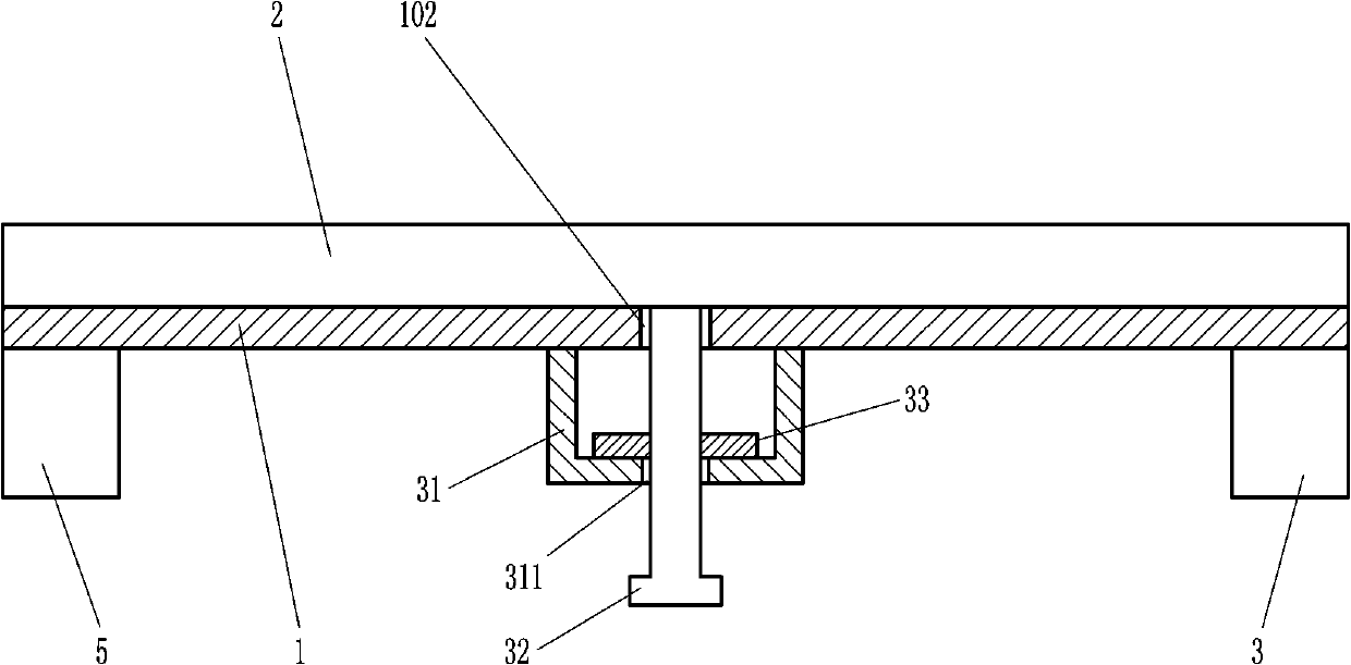
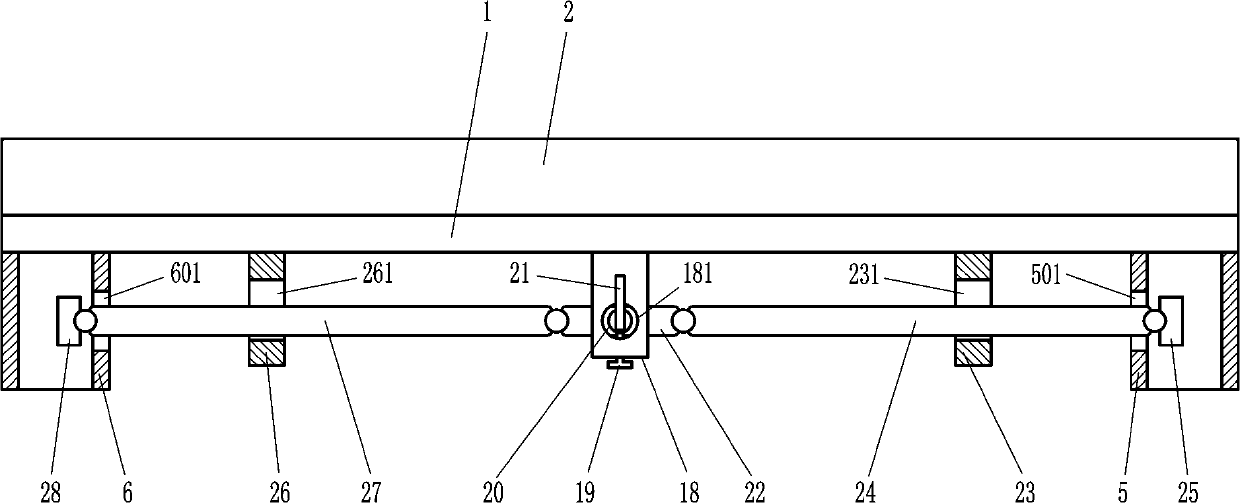
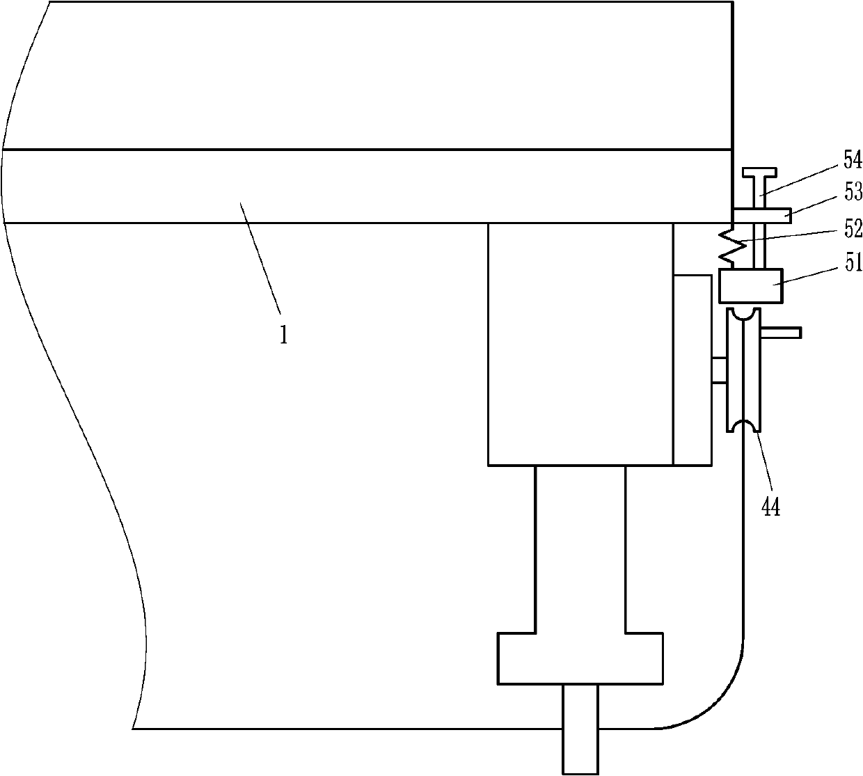
[0026] A connecting device for table tops and table legs, such as Figure 1-8 As shown, it includes a pallet 1, a rectangular frame plate 2, a first rectangular cannula 3, a second rectangular cannula 4, a third rectangular cannula 5, a fourth rectangular cannula 6, a first fixing plate 7, a first rectangular cannula Screw rod 8, first rotating shaft 9, first driving rod 10, first rotating plate 11, first guide block 12, first connecting rod 13, first pressing block 14, second guiding block 15, second connecting rod 16 , the second pressing block 17, the second fixing plate 18, the second screw rod 19, the second rotating shaft 20, the second driving rod 21, the second rotating plate 22, the third guide block 23, the third connecting rod 24, the third Press block 25, the fourth guide block 26, the fourth connecting rod 27 and the fourth press block 28, the supporting plate 1 has a large rectangular groove 101, a left through hole 102 and a right through hole 103, the left thro...

Embodiment 2

[0028] A connecting device for table tops and table legs, such as Figure 1-8 As shown, it includes a pallet 1, a rectangular frame plate 2, a first rectangular cannula 3, a second rectangular cannula 4, a third rectangular cannula 5, a fourth rectangular cannula 6, a first fixing plate 7, a first rectangular cannula Screw rod 8, first rotating shaft 9, first driving rod 10, first rotating plate 11, first guide block 12, first connecting rod 13, first pressing block 14, second guiding block 15, second connecting rod 16 , the second pressing block 17, the second fixing plate 18, the second screw rod 19, the second rotating shaft 20, the second driving rod 21, the second rotating plate 22, the third guide block 23, the third connecting rod 24, the third Press block 25, the fourth guide block 26, the fourth connecting rod 27 and the fourth press block 28, the supporting plate 1 has a large rectangular groove 101, a left through hole 102 and a right through hole 103, the left thro...

Embodiment 3

[0031] A connecting device for table tops and table legs, such as Figure 1-8 As shown, it includes a pallet 1, a rectangular frame plate 2, a first rectangular cannula 3, a second rectangular cannula 4, a third rectangular cannula 5, a fourth rectangular cannula 6, a first fixing plate 7, a first rectangular cannula Screw rod 8, first rotating shaft 9, first driving rod 10, first rotating plate 11, first guide block 12, first connecting rod 13, first pressing block 14, second guiding block 15, second connecting rod 16 , the second pressing block 17, the second fixing plate 18, the second screw rod 19, the second rotating shaft 20, the second driving rod 21, the second rotating plate 22, the third guide block 23, the third connecting rod 24, the third Press block 25, the fourth guide block 26, the fourth connecting rod 27 and the fourth press block 28, the supporting plate 1 has a large rectangular groove 101, a left through hole 102 and a right through hole 103, the left thro...


PUM


Abstract

The invention relates to a connecting device and particularly relates to a connecting device for a desk plate and desk legs. The connecting device can be used for fixing the desk plate and the desk legs and is safe and reliable. According to the technical scheme, the connecting device comprises a support plate, a rectangular frame plate, a first rectangular insertion pipe, a second rectangular insertion pipe, a third rectangular insertion pipe, a fourth rectangular insertion pipe, a first fixed plate, a first screw rod and the like, wherein a big rectangular slot, a left through hole and a right through hole are longitudinally penetratingly formed in the support plate, the left through hole is located on the left side of the big rectangular slot, and the right through hole is located on the right side of the big rectangular slot. According to the connecting device, the desk plate and the desk legs can be firmly combined together, so that the situation that the desk plate falls from thedesk legs to smash a user and the floor can be avoided, and the life and property of people can be protected; and the connecting device is convenient to dismount and mount, simple in structure and easy to produce, manufacture, maintain and repair.

Description

technical field [0001] The invention relates to a connecting device, in particular to a connecting device for a table board and a table leg. Background technique [0002] The table board is used to support and place items and for people to handle copywriting. The table legs provide fixed support for the table board. At present, people usually place the table board directly on the table legs in the market without any fixing measures. As a result, the table board is easy to fall from the table legs. The heavy table board is not only easy to smash the floor, causing serious economic losses, but also easy to hit the user, causing a serious threat to people's life safety, which is not conducive to people's safety. Life. Contents of the invention [0003] In order to overcome the fact that people usually place the table board directly on the table legs in the current market without any fixing measures, the table board is easy to fall from the table legs, and the heavy table boa...

Claims


Application Information

Patent Timeline
Patent Type & Authority Applications(China)
IPC IPC(8): A47B13/00F16B12/02
CPCA47B13/003F16B12/02
Inventor 魏元鹏
Owner 赣州市港汇机电设备有限公司
Why Eureka
Try Eureka