Streetlamp device and mounting method

A technology of street lamps and mounting boards, which is applied in the direction of lighting devices, fixed lighting devices, lighting auxiliary devices, etc. good effect

Pending Publication Date: 2019-08-02
扬州唯一景观工程有限公司
View PDF0 Cites 0 Cited by
  • Summary
  • Abstract
  • Description
  • Claims
  • Application Information

AI Technical Summary

Problems solved by technology

The lamp arm and the rod body of the existing street lamps are usually connected by welding. After the lamp arm and the rod body are welded and connected, the angle of the lamp arm is fixed and cannot be adjusted. As a result, the illumination angle of the lamps of the existing street lamps is also fixed and cannot be adjusted. , which also leads to a relatively limited range of use of the existing street lamp structure. For projects with different irradiation angle requirements, it is necessary to design a corresponding structural form, which increases the design and manufacturing costs.
Street lights mainly provide lighting for pedestrians on the road at night, and do not need to provide lighting during the day. The existing street light structure has no corresponding protective measures for the lamps, resulting in the lamps being exposed to the external environment for a long time no matter day or night. It is very easy to cause damage to the lamp. Although the lamp is equipped with a lamp housing, compared with the rod body, the lamp is equipped with more wearing parts. Under the same external environment, the service life of the lamp will be shorter, more easily damaged, and increase The daily maintenance cost of lamps and lanterns is reduced

Method used


Image

  • Streetlamp device and mounting method
  • Streetlamp device and mounting method
  • Streetlamp device and mounting method

Examples


Embodiment Construction

[0028] The following will clearly and completely describe the technical solutions in the embodiments of the present invention with reference to the accompanying drawings in the embodiments of the present invention. Obviously, the described embodiments are only some, not all, embodiments of the present invention. Based on the embodiments of the present invention, all other embodiments obtained by persons of ordinary skill in the art without making creative efforts belong to the protection scope of the present invention.

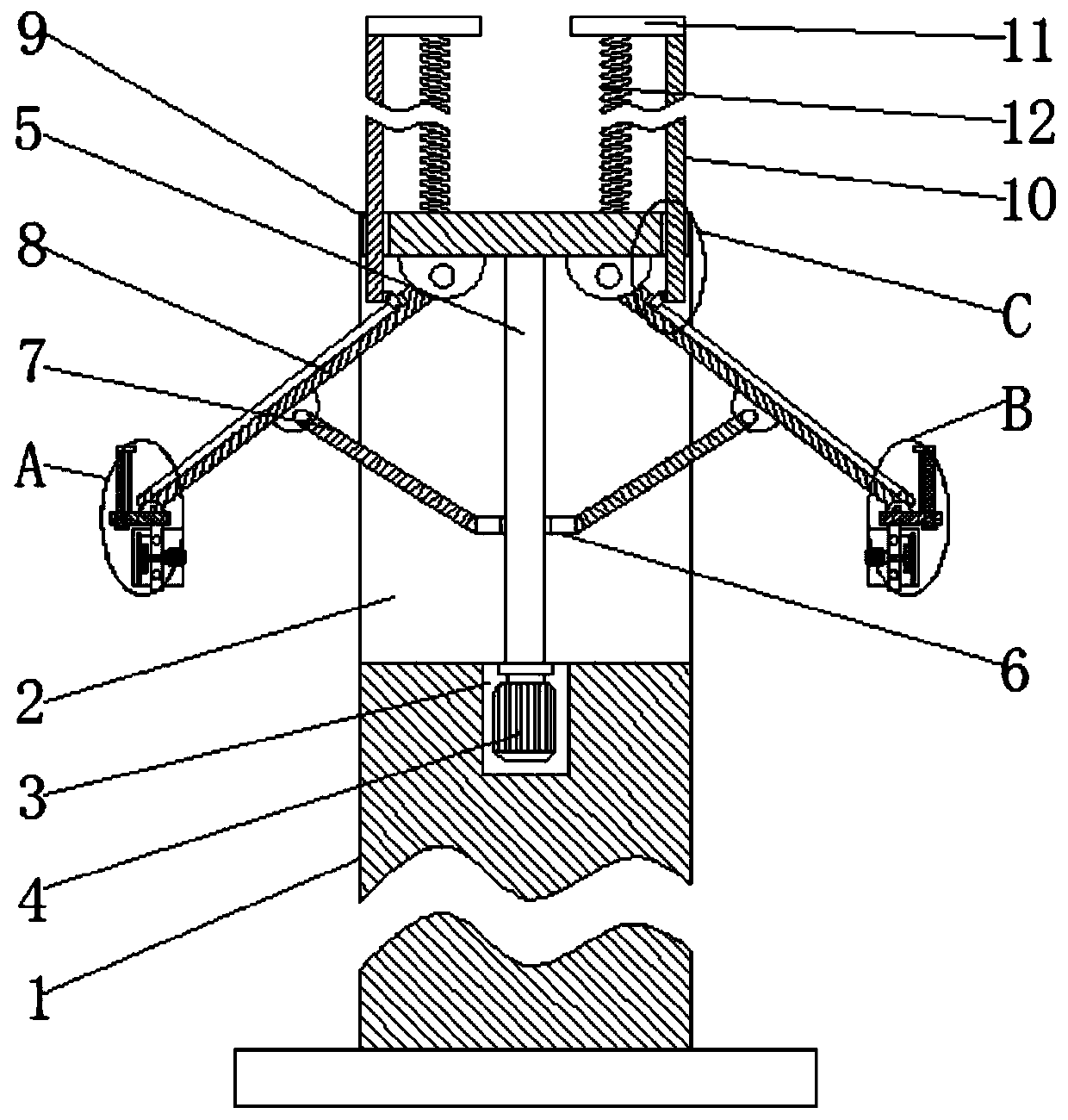
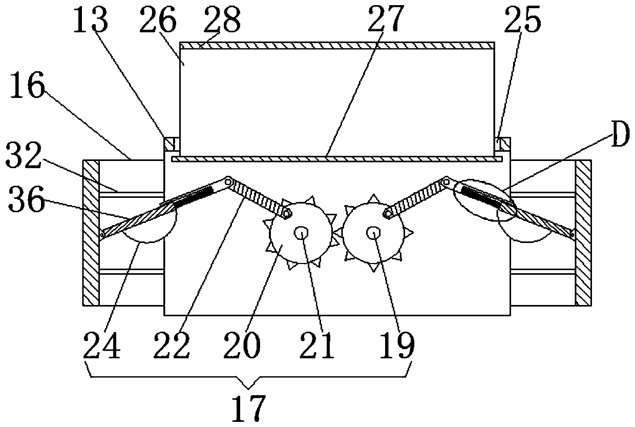
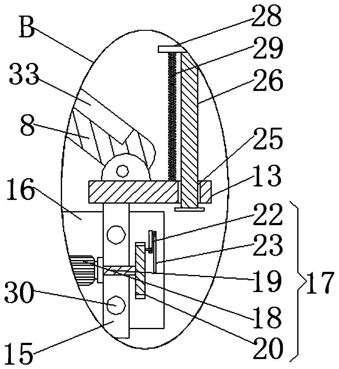
[0029] see Figure 1-6, the present invention provides a technical solution: a street light device, including a light pole 1, a rectangular groove 2 is opened on the side wall of the light pole 1 close to the top surface, the rectangular groove 2 is set through the left and right side walls of the light pole 1, and the rectangular groove The bottom surface of 2 is provided with groove 3, and groove 3 is provided with first motor 4, is fixedly connected between...


PUM


Abstract

The invention discloses a streetlamp device and a mounting method, and belongs to the technical field of road illumination devices. The streetlamp device comprises a lamp pole, wherein a rectangular groove is formed in the side wall, close to the top face, of the lamp pole; a groove is formed in the bottom face of the rectangular groove; a first motor is arranged in the groove; a rotor of the first motor is fixedly connected with a threaded rod; a movable plate is arranged on the threaded rod; the left side wall and the right side wall of the movable plate are movably connected with a first connecting rod; one side, far away from the movable plate, of the first connecting rod is movably connected with a second connecting rod; the bottom face of the second connecting rod is movably connected with a mounting plate; the bottom face of the mounting plate is fixedly connected with a fixed plate; and an adjusting device is arranged on the fixed plate. According to the streetlamp device and the mounting method disclosed by the invention, an adjustment operation of an illumination direction can be realized, and an application range of streetlamps is widened, so that damage of an external environment to an LED light source is effectively avoided, a protection effect is good, and the service life of the LED light source is prolonged.

Description

technical field [0001] The invention relates to the technical field of road lighting devices, in particular to a street lamp device and an installation method. Background technique [0002] Street lamp is the main component of road lighting facilities. The existing street lamp structure usually consists of a rod body, a lamp arm and a lamp (or LED light source). The lamp arm is installed on the top of the rod body, and the lamp is installed at the end of the lamp arm. The lamp arm and the rod body of the existing street lamps are usually connected by welding. After the lamp arm and the rod body are welded and connected, the angle of the lamp arm is fixed and cannot be adjusted. As a result, the illumination angle of the lamps of the existing street lamps is also fixed and cannot be adjusted. , which also leads to a relatively limited range of use of the existing street lamp structure. For projects with different irradiation angle requirements, it is necessary to design corre...

Claims


Application Information

Patent Timeline
Patent Type & Authority Applications(China)
IPC IPC(8): F21S8/08F21V21/14F21V21/15F21V21/26F21V15/01F21Y115/10
CPCF21S8/08F21V15/01F21V21/14F21V21/15F21V21/26F21Y2115/10
Inventor 李玉杰
Owner 扬州唯一景观工程有限公司
Why Eureka
Try Eureka