air scrubber

An air washing and air technology, applied in air humidification systems, air quality improvement, air conditioning systems, etc., can solve problems such as not meeting hygiene requirements

Active Publication Date: 2022-03-25
BONECO AG
View PDF10 Cites 0 Cited by
  • Summary
  • Abstract
  • Description
  • Claims
  • Application Information

AI Technical Summary

Problems solved by technology

Even though this is perfectly valid, the operation does not meet all requirements for hygiene

Method used


Image

  • air scrubber
  • air scrubber
  • air scrubber

Examples


Embodiment Construction

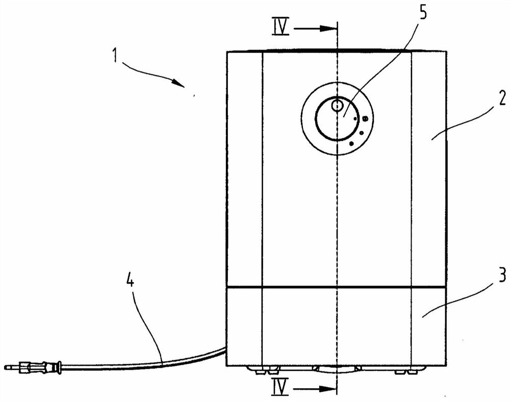
[0059] exist figure 1 The air washer 1 shown in has a housing consisting of an upper housing part 2 and a lower housing part 3 . The air scrubber can be connected to the grid via a power cable 4 which preferably leads along the housing lower part 2 into the housing upper part. The air scrubber can be put into operation via one or more operating elements 5 .

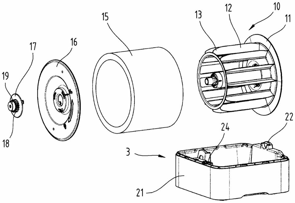
[0060] figure 2 The housing lower part 3 and the parts present therein are shown in an exploded view. The lower part of the housing forms the water tanks 20, 21 for the water to be evaporated. After the housing upper part has been removed, the tank can be easily filled from above, wherein the removal of the rollers 10 to 19 is not absolutely necessary for this.

[0061] The sinks 20, 21 are produced, for example, from a suitable plastic.

[0062] A receptacle 22 for a pivot pin 19 of the drums 10 to 19 is provided on both sides on the water troughs 20 , 21 . Furthermore, there are two electrical contacts 24, for ex...


PUM


Abstract

According to one aspect of the invention there is provided an air scrubber comprising an electrically driven fan (41) and a drum (10 to 19) with a belt forming a closed loop surrounding the pad (15) for the support of the roller. The mat (15) can be rotated electrically about an axis of rotation, wherein the lower part of the roller (10 to 19) is submerged in a water tank (20, 21). The mat (15) can be removed from the roller (10 to 19) by movement in the axial direction and can be pushed back onto the roller by movement in the axial direction.

Description

technical field [0001] The present invention relates to an air scrubber. Background technique [0002] Pollutants in the air like dust, pollen, bacteria etc. mean a burden to some people. For this reason, there are appliances known as "air scrubbers". In the air scrubber, an air stream can be brought into contact with water, which can be doped with active substances and / or fragrances. This has the result that, firstly, pollutants present in particular as solid particles remain in the water and secondly, the air is humidified, which also has a positive effect on the room climate. [0003] For air scrubbers, the principle of guiding the air flow by wetted components, in particular components made of hygroscopic materials immersed in water, is known. In this case, the air can emit pollutants and, depending on the air humidity already present, absorb moisture. In such air scrubbers, for reasons of efficiency it is important that the air flow on the one hand comes into contac...

Claims


Application Information

Patent Timeline
Patent Type & Authority Patents(China)
IPC IPC(8): F24F8/125F24F6/06F24F8/80
CPCB01D47/02F24F6/06F24F2006/065F24F8/125F24F8/80B01D47/027B01D47/18B01D2247/14Y02A50/20F24F8/10B01D47/024B01D33/073B01D47/00B01D33/06B01F23/20B01F23/21B01F23/215
Inventor M·菲茨
Owner BONECO AG
Why Eureka
Try Eureka