A horizontally movable three-dimensional acquisition device

A collection device and horizontal movement technology, applied in the direction of using optical devices, measuring devices, instruments, etc., can solve the problems of expensive equipment, inoperable, difficult installation and debugging of equipment, etc., to achieve speed and effect, and convenient for outdoor use. , optimize the effect of camera position

Active Publication Date: 2020-11-17
天目爱视(北京)科技有限公司
View PDF7 Cites 0 Cited by
  • Summary
  • Abstract
  • Description
  • Claims
  • Application Information

AI Technical Summary

Problems solved by technology

But even with such a device, it can only collect 3D information of human-sized objects, and it can only be used indoors
At the same time, the use of a large number of cameras makes the installation and debugging of the entire equipment very difficult, and the equipment is very expensive
Moreover, the current acquisition equipment is designed for a single size, once the size of the object changes greatly, it will not work
[0003] At the same time, in order to take into account the combination speed and effect, the field uses empirical formulas including rotation angle, target object size, and object distance to limit the camera position. However, in practical applications, it is found that unless there is a precise angle measuring device, the user is not sensitive to the angle. It is difficult to accurately determine the angle; the size of the target is difficult to determine accurately, especially in some applications where the target needs to be replaced frequently, each measurement brings a lot of extra workload, and professional equipment is required to accurately measure irregular targets
Measurement errors lead to camera position setting errors, which will affect the speed and effect of acquisition and synthesis; the accuracy and speed need to be further improved

Method used


Image

  • A horizontally movable three-dimensional acquisition device
  • A horizontally movable three-dimensional acquisition device
  • A horizontally movable three-dimensional acquisition device

Examples


Embodiment Construction

[0032] Exemplary embodiments of the present disclosure will be described in more detail below with reference to the accompanying drawings. Although exemplary embodiments of the present disclosure are shown in the drawings, it should be understood that the present disclosure may be embodied in various forms and should not be limited by the embodiments set forth herein. Rather, these embodiments are provided for more thorough understanding of the present disclosure and to fully convey the scope of the present disclosure to those skilled in the art.

[0033] Device structure

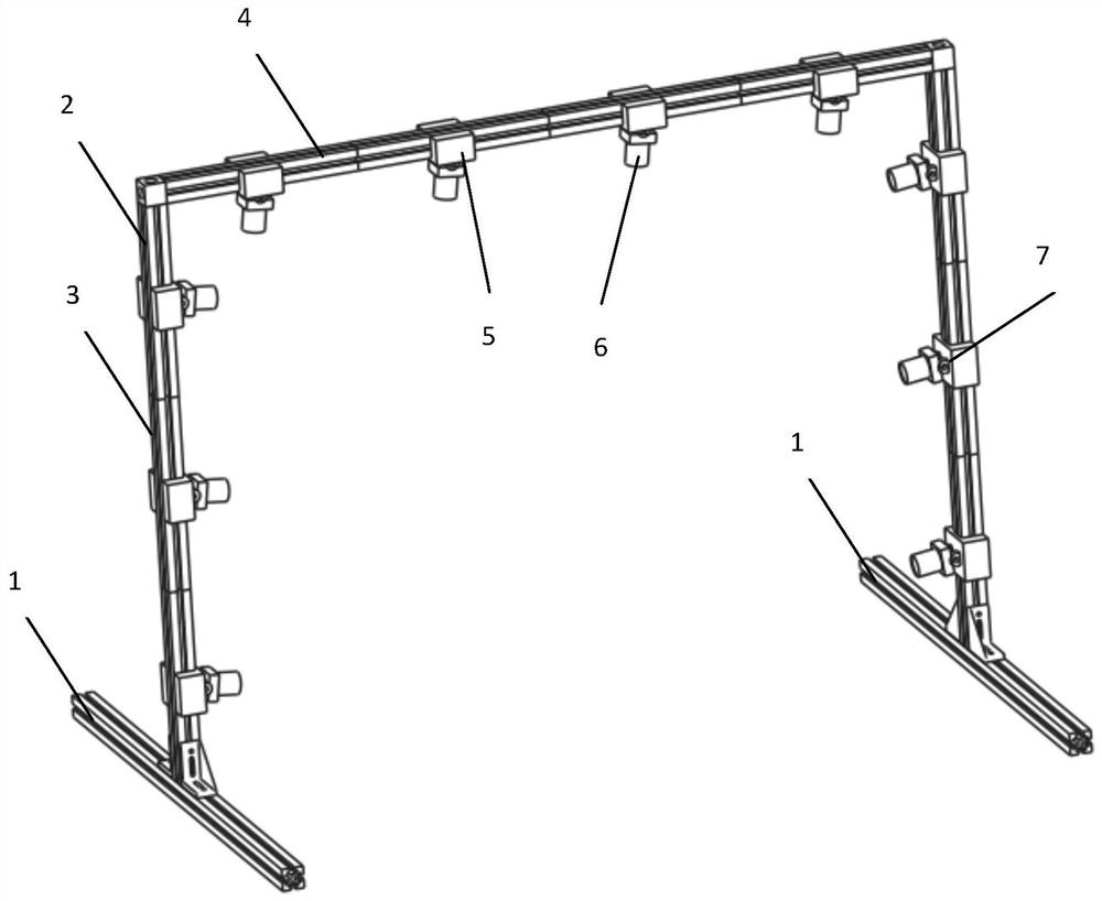
[0034] In order to solve the above technical problems, an embodiment of the present invention provides a horizontally movable three-dimensional acquisition device. Such as figure 1 As shown, it specifically includes: a horizontal track 1 and an acquisition frame 2.

[0035] Wherein the acquisition frame is a gantry type, including a column 3 and a beam 4. The column is composed of multiple sections, ...


PUM


Abstract

The invention provides a three-dimensional acquisition device capable of horizontally moving, which comprises a horizontal rail and an acquisition frame, wherein the acquisition frame is movably connected with the horizontal rail; the acquisition frame comprises a stand column and a cross beam, and an image acquisition device is arranged on the acquisition frame; and the image acquisition device is connected with the acquisition frame. In the invention, a gantry support structure is adopted for the first time, so that three-dimensional information of a large object can be collected. The gantrysupport can be disassembled and expanded, can adapt to objects with different sizes, and is convenient to disassemble and assemble.

Description

technical field [0001] The invention relates to the technical field of object measurement, in particular to the technical field of using images to perform 3D acquisition of objects and measurement of geometric dimensions such as length. Background technique [0002] At present, laser scanning is usually used for 3D acquisition of large objects, but laser scanning requires special calibration of the object, setting multiple calibration points on the object, and the calibration process is cumbersome. For example, when scanning the vehicle shell, the use of laser scanners relies too much on the calibration accuracy, so the entire calibration work will last for one or two days, and the work efficiency is extremely low. And it is not suitable for outdoor operation due to weather changes. However, traditional devices that use image photography for 3D acquisition are usually only suitable for capturing small objects. In order to photograph larger objects, corresponding exploratio...

Claims


Application Information

Patent Timeline
Patent Type & Authority Patents(China)
IPC IPC(8): G01B11/24F16M13/02F16M11/04F16M11/12F16M11/18G01B11/00
CPCF16M11/045F16M11/046F16M11/12F16M11/18F16M13/005F16M13/02G01B11/00
Inventor 左忠斌左达宇
Owner 天目爱视(北京)科技有限公司
Why Eureka
Try Eureka