Unlock instant, AI-driven research and patent intelligence for your innovation.
Distributed Fiber Optic Acoustic and Vibration Fusion Sensing System
What is Al technical title?
Al technical title is built by PatSnap Al team. It summarizes the technical point description of the patent document.
A technology of distributed optical fiber and sensing system, applied in the direction of measuring ultrasonic/sound wave/infrasonic wave, using wave/particle radiation, instruments, etc., can solve the problem of single vibration or sound wave sensing, etc., and achieve cost saving, convenient use, and easy operation flexible effects
Active Publication Date: 2022-04-22
武汉光谷航天三江激光产业技术研究院有限公司
View PDF11 Cites 0 Cited by
Summary
Abstract
Description
Claims
Application Information
AI Technical Summary
This helps you quickly interpret patents by identifying the three key elements:
Problems solved by technology
Method used
Benefits of technology
Problems solved by technology
[0005] In order to overcome the shortcomings of conventional distributed optical fiber sensing equipment that only has a single vibration or acoustic wave sensing, the present invention provides a distributed optical fiber acoustic wave and vibration fusion sensing system, which integrates two functions of vibration and acoustic wave sensing
Method used
Image
Click on the blue label to locate the original text in one second.
Reading with bidirectional positioning of images and text.
Examples
Embodiment 1
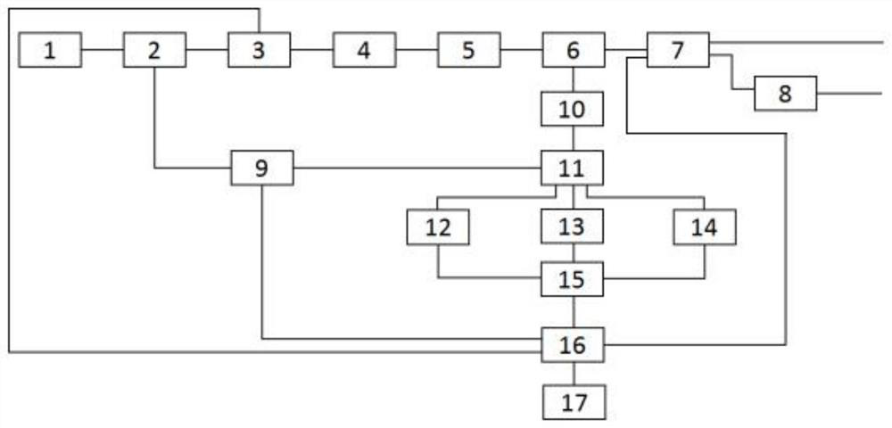
[0023] A distributed optical fiber acoustic wave and vibration fusion sensing system of the present invention, its structure includes a laser 1, a 1×2 optical fiber coupler 2, an acousto-optic modulator 3, an erbium-doped optical fiber amplifier 4, a first optical fiber filter 5, Optical fiber circulator 6, first optical switch, optical fiber Raman amplifier 8, second optical switch 9, second optical fiber filter 10, 3×3 optical fiber coupler 11, first photodetector 12, second photodetector 13 , the third photodetector 14, data acquisition and processing unit 15, computer 16, host computer software 17;
[0024] The laser 1, the 1×2 fiber coupler 2, the acousto-optic modulator 3, the erbium-doped fiber amplifier 4, the first fiber filter 5, the fiber circulator 6, the first optical switch, and the fiber Raman amplifier 8 pass through a single mode optical fiber, the optical fiber circulator 6, the second optical fiber filter 10, the 3×3 optical fiber coupler 11, the first photo...
Embodiment 2
[0044] Compared with Embodiment 1, the difference is that the laser 1 is a narrow linewidth laser.
[0045] All the other contents are the same as in Example 1.
Embodiment 3
[0047] Compared with Embodiment 2, the difference is that the power splitting ratio of the 1×2 fiber coupler 2 is 1:99, and the output power ratio of the first output port of the 1×2 fiber coupler 2 is 99. %, the output power ratio of the second output port of the 1×2 fiber coupler 2 is 1%.
[0048] All the other contents are identical with embodiment 2.
PUM
Abstract
The distributed optical fiber acoustic wave and vibration fusion sensing system of the present invention includes a laser, a 1×2 optical fiber coupler, an acousto-optic modulator, an erbium-doped optical fiber amplifier, a first optical fiber filter, an optical fiber circulator, a first optical switch, Optical fiber Raman amplifier, second optical switch, second optical fiber filter, 3×3 optical fiber coupler, first photodetector, second photodetector, third photodetector, data acquisition and processing unit, computer, host machine software. Advantages: The system combines two sensing functions and modes of vibration and sound wave sensing, which can meet different work requirements, effectively overcome the shortcomings of conventional distributed optical fiber sensing equipment with only single vibration or sound wave sensing, and save costs , is an important technical improvement in the field of distributed optical fiber sensing; it can be flexibly switched according to different usage requirements and scenarios, saving costs and easy to use; it proposes a way to control the optical switch to switch between vibration and acoustic sensing modes, and the operation is flexible.
Description
technical field [0001] The invention relates to the field of optical fiber sensing, in particular to a distributed optical fiber acoustic wave and vibration fusion type sensing system. Background technique [0002] Optical fiber sensor consists of light source, detection fiber, light modulator, light detector and demodulator. Its working process is to send the light of the light source into the modulation area through the incident optical fiber, and the light interacts with the external measured parameters in the modulation area to make the optical properties of the light (such as intensity, wavelength, frequency, phase, partial normal state, etc.) occur. It becomes modulated signal light, which is then sent to the optical detector and demodulator through the outgoing fiber to obtain the measured parameters. [0003] Distributed optical fiber sensor is a sensor that uses unique distributed optical fiber detection technology to measure or monitor the spatial distribution and...
Claims
Application Information
Patent Timeline
Application Date:The date an application was filed.
Publication Date:The date a patent or application was officially published.
First Publication Date:The earliest publication date of a patent with the same application number.
Issue Date:Publication date of the patent grant document.
PCT Entry Date:The Entry date of PCT National Phase.
Estimated Expiry Date:The statutory expiry date of a patent right according to the Patent Law, and it is the longest term of protection that the patent right can achieve without the termination of the patent right due to other reasons(Term extension factor has been taken into account ).
Invalid Date:Actual expiry date is based on effective date or publication date of legal transaction data of invalid patent.
