Method, device and electronic equipment for determining pulse collection point

A technology for collecting points and pulses, which is applied in the field of digital pulse diagnosis, can solve problems affecting the accuracy of digital pulse diagnosis, and achieve the effects of improving positioning accuracy, more accurate collection positions, and more accurate collection positions

Active Publication Date: 2021-11-05
TIANJIN MEDVALLEY TECH CO LTD
View PDF11 Cites 0 Cited by
  • Summary
  • Abstract
  • Description
  • Claims
  • Application Information

AI Technical Summary

Problems solved by technology

However, due to the different shapes of each person's arms, manual confirmation of the pulse collection position requires a certain amount of experience accumulation. If the collection position deviates greatly, it will seriously affect the accuracy of digital pulse diagnosis

Method used


Image

  • Method, device and electronic equipment for determining pulse collection point
  • Method, device and electronic equipment for determining pulse collection point
  • Method, device and electronic equipment for determining pulse collection point

Examples


Embodiment 1

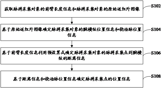
[0030] figure 1 A flowchart of a method for determining a pulse collection point provided by an embodiment of the present invention, such as figure 1 As shown, the method specifically includes the following steps:

[0031]Step S102, acquiring the forearm length information of the pulse collection object and the original near-infrared image of the pulse collection object.

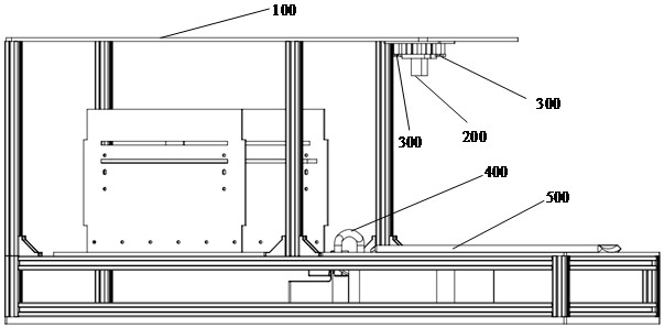
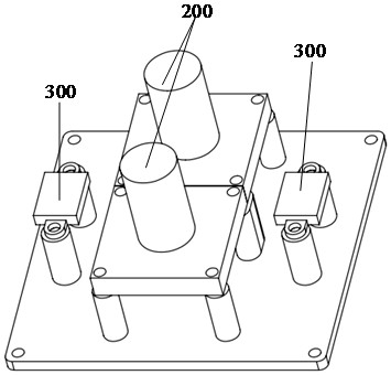
[0032] Specifically, the execution subject of the method of the present invention is the central processing unit in the pulse collection point positioning device, and the device also includes: a near-infrared camera, a laser ranging sensor, a near-infrared supplementary light source and a wrist posture adjustment mechanism in addition to the central processing unit etc., the structure of the device will be introduced below. The device can realize the acquisition of near-infrared images and the determination of pulse collection points, wherein the pulse collection points include: the Cunguan ruler on the ra...

Embodiment 2

[0104]The embodiment of the present invention also provides a device for determining a pulse collection point. The device for determining a pulse collection point is mainly used to implement the method for determining a pulse collection point provided in the first embodiment above. A device for determining a pulse collection point is introduced in detail.

[0105] Figure 4 It is a functional block diagram of a device for determining a pulse collection point provided by an embodiment of the present invention, as shown in Figure 4 As shown, the device mainly includes: a first acquisition module 10, a first determination module 20, a second determination module 30, and a third determination module 40, wherein:

[0106] The first acquisition module 10 is used to acquire the forearm length information of the pulse acquisition object and the original near-infrared image of the pulse acquisition object; wherein, the original near-infrared image includes the arm near-infrared image...

Embodiment 3

[0144] see Figure 5 , the embodiment of the present invention provides an electronic device, the electronic device includes: a processor 60, a memory 61, a bus 62 and a communication interface 63, the processor 60, the communication interface 63 and the memory 61 are connected through the bus 62; the processor 60 is used to execute executable modules, such as computer programs, stored in memory 61 .

[0145] Wherein, the memory 61 may include a high-speed random access memory (RAM, RandomAccessMemory), and may also include a non-volatile memory (non-volatile memory), such as at least one disk memory. The communication connection between the system network element and at least one other network element is realized through at least one communication interface 63 (which may be wired or wireless), and the Internet, wide area network, local network, metropolitan area network, etc. can be used.

[0146] The bus 62 can be an ISA bus, a PCI bus or an EISA bus, etc. The bus can be d...


PUM


Abstract

The invention provides a method, device and electronic equipment for determining a pulse collection point, and relates to the technical field of digital pulse diagnosis, including: obtaining the forearm length information and the original near-infrared image of the pulse collection object, wherein the original near-infrared image includes arm A near-infrared image, and the vascular area of ​​the wrist radial artery in the original near-infrared image is greater than the preset threshold; the position information of the wrist stripes and the position information of the radial artery are determined based on the original near-infrared image, and the preset calculation formula is used according to the forearm length information Determine the distance information from the pulse collection point to the wrist crease; determine the position information of the pulse collection point according to the distance information and radial artery position information. The present invention uses a scientific method to process the original near-infrared image, and finally determines the position information of the pulse collection point. Compared with the traditional method of manually confirming the patient's pulse collection position, it has the advantage of more accurate collection position and effectively improves the pulse collection point. Positioning accuracy of pulse collection point.

Description

technical field [0001] The invention relates to the technical field of digital pulse diagnosis, in particular to a method, device and electronic equipment for determining a pulse collection point. Background technique [0002] In the academic circle of Chinese medicine, the collection of pulse information is also called feeling the pulse or calling the pulse, which is an indispensable link in the dialectical process of TCM treatment. The traditional method of pulse collection relies on the front of the finger of the doctor of traditional Chinese medicine to touch the skin at the radial artery of the patient's wrist. After applying a certain pressure to the patient's skin, obtain information such as the pulse force and frequency of the patient's artery, and draw conclusions based on his own experience. The premise of obtaining correct and objective pulse information through the above methods requires long-term experience accumulation, which hinders the inheritance and develop...

Claims


Application Information

Patent Timeline
Patent Type & Authority Patents(China)
IPC IPC(8): A61B5/00
CPCA61B5/0033A61B5/0077A61B5/489
Inventor 王永恒赵亮赵晓萌董玉舒
Owner TIANJIN MEDVALLEY TECH CO LTD
Why Eureka
Try Eureka