

Electric connector
A technology of electrical connectors and connecting sections, applied in the direction of conductive connection, connection, three-pole connection, etc., to achieve the effect of size reduction
- Summary
- Abstract
- Description
- Claims
- Application Information
AI Technical Summary
Problems solved by technology
Method used
Image

Examples
Embodiment Construction
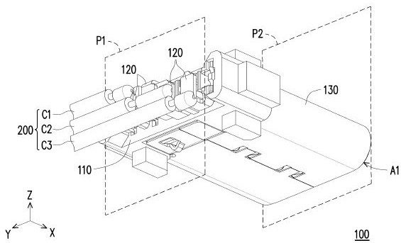
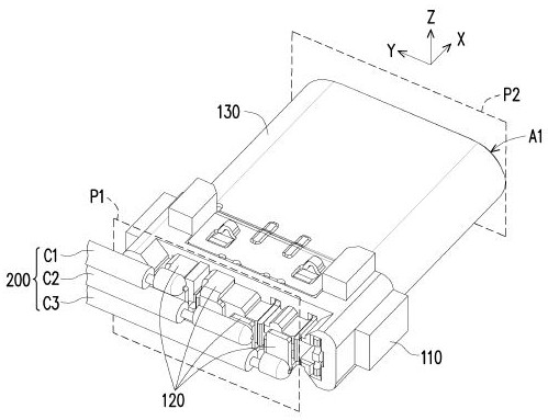
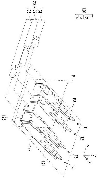
[0038] Figure 1A is a schematic diagram of an electrical connector according to an embodiment of the present invention. Figure 1B draw from another perspective Figure 1A of electrical connectors. figure 2 It is a schematic diagram of the assembly of some components of the electrical connector in FIG. 1 . Cartesian coordinates X-Y-Z are also provided here to facilitate component description. Please also refer to Figure 1A , Figure 1B and figure 2 , in this embodiment, the electrical connector 100 is used for welding the cable 200 . The electrical connector 100 includes an insulating body 110 , a plurality of terminals 120 and a housing 130 . The terminals 120 are arranged laterally and disposed on the insulating body 110 . Each terminal 120 has a butt section 121 , a connection section 122 and a welding section 123 . The shell 130 is assembled on the insulating body 110 to form an interface A1 for docking with another electrical connector (not shown). For the term...
PUM
 Abstract
Description
Claims
Application Information