Electric tightening machine

An electric and electric push rod technology, applied in solid separation, chemical instruments and methods, grids, etc., can solve the problems of large equipment space, low efficiency, high labor intensity, etc., and achieve the effect of small space occupation

Pending Publication Date: 2022-05-27
LIAOYUAN RUIYI GRAIN MACHINERY MFG +1
View PDF0 Cites 0 Cited by
  • Summary
  • Abstract
  • Description
  • Claims
  • Application Information

AI Technical Summary

Problems solved by technology

The frame of the traditional stretching machine is a fixed structure, which has restrictions on the size of the sieve core to be placed. If the size of the sieve core is too small, the pulling angle becomes smaller, and it is difficult to guarantee the gold sticking force. Therefore, the traditional stretching machine is only suitable for one size and type of sieve. grid manufacturing
In addition, the pulling mechanism in the traditional stretch-mounting machine includes manual drive and pneumatic drive. The manual drive is not only inefficient, but also labor-intensive. The structure of the pneumatic system is complex and the equipment takes up a lot of space.

Method used


Image

  • Electric tightening machine
  • Electric tightening machine
  • Electric tightening machine

Examples


Embodiment Construction

[0016] The technical solutions in the embodiments of the present invention will be clearly and completely described below with reference to the accompanying drawings in the embodiments of the present invention. Obviously, the described embodiments are only a part of the embodiments of the present invention, rather than all the embodiments. Based on the embodiments of the present invention, all other embodiments obtained by those of ordinary skill in the art without creative efforts shall fall within the protection scope of the present invention.

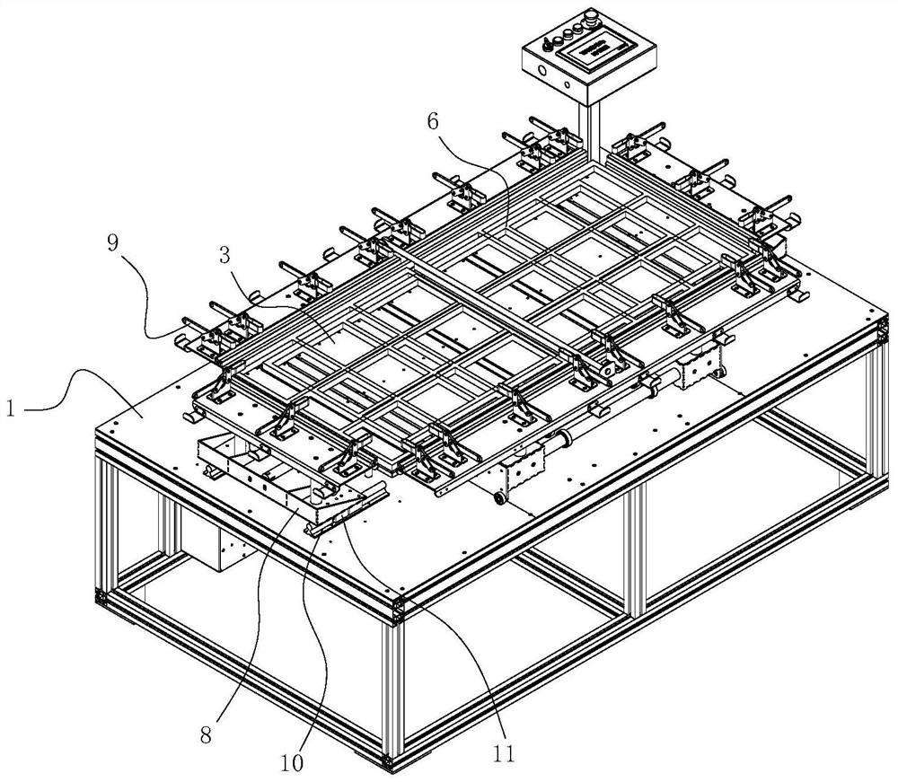
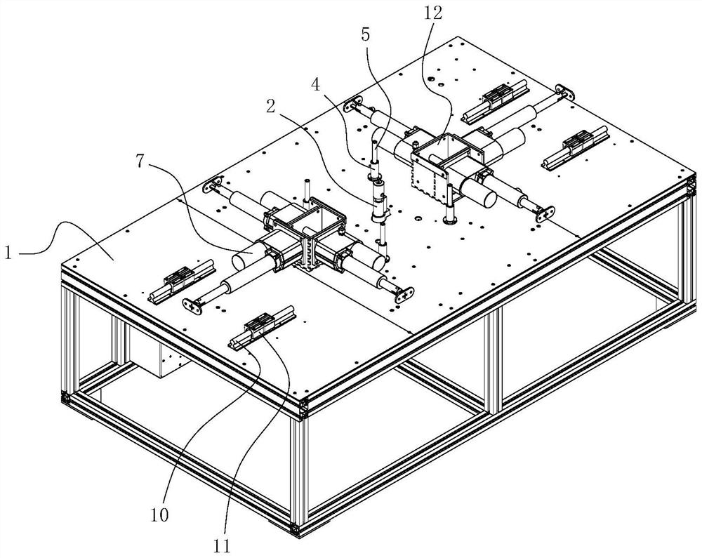
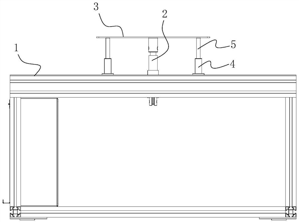
[0017] see Figure 1-4 , the present invention provides the following technical solutions: an electric stretching machine, comprising a working platform 1, and the working platform 1 is a flat plate fixed on a frame body composed of aluminum profiles. The middle of the working platform 1 is installed with a vertical lifting electric push rod 2, a through hole is opened in the middle of the working platform 1, and a metal bracket is i...


PUM


Abstract

An electric tightening machine comprises a working platform, a lifting electric push rod arranged in the vertical direction is installed in the middle of the working platform, the lifting electric push rod is provided with a vertical ejector rod vertically extending upwards, and a lifting flat plate is installed at the upper end of the vertical ejector rod; horizontal electric push rods are arranged on the working platform and located on the periphery of the lifting electric push rod, the horizontal electric push rods are provided with transverse ejector rods extending towards the four sides of the lifting flat plate, the transverse ejector rods are provided with horizontal movable frames, and the horizontal movable frames are provided with a plurality of clamps. And the clamps are uniformly distributed along a straight line parallel to the corresponding side edge of the lifting flat plate. The tightening machine can be suitable for manufacturing more screens of different sizes and models, and the occupied space of a component system is small.

Description

technical field [0001] The invention belongs to the technical field of screen grid manufacturing equipment, and in particular relates to an electric stretching machine. Background technique [0002] The stretcher is an auxiliary equipment for the manufacture of screen grids. It applies the screen surface tension to the screen and the bonding force between the screen surface and the screen core. [0003] At present, the structure of the stretching machine includes a frame for supporting and placing the screen core, and a pulling mechanism is provided around the frame for holding the screen mesh and applying a transverse horizontal pulling force to the screen mesh to make the screen mesh have plane tension. The pulling mechanism is close to the edge of the screen core, and the height of the edge of the screen that is pulled is lower than the height of the upper edge of the screen core. When the screen is pulled, due to the existence of the screen pulling angle at the edge of ...

Claims


Application Information

Patent Timeline
Patent Type & Authority Applications(China)
IPC IPC(8): B07B1/48
CPCB07B1/48
Inventor 戚光远刘栋华刘文春刘玉普成汉文王艺澎马成成刘春生张洁
Owner LIAOYUAN RUIYI GRAIN MACHINERY MFG
Why Eureka
Try Eureka