Fuel pump assembly

A technology of fuel pumps and components, which is applied in the direction of fuel injection pumps, fuel injection devices, liquid fuel feeders, etc., and can solve the problems of engine fuel supply performance impact, increased assembly steps, time-consuming and expensive problems, etc.

Inactive Publication Date: 2003-04-09
HONDA MOTOR CO LTD
View PDF0 Cites 0 Cited by
  • Summary
  • Abstract
  • Description
  • Claims
  • Application Information

AI Technical Summary

Problems solved by technology

[0010] However, the above method of changing the fuel pump and pressure regulator is time-consuming and expensive, resulting in increased cost of the fuel pump
In addition, I am afraid that there will be a negative impact on the performance of the engine for fueling at the necessary speed
[0011] In contrast, although the method of adding a rubber pad is relatively easy, it also increases the number of parts such as the rubber pad, and therefore, a method of attempting to enlarge the fuel pump assembly 102 and the fuel tank 101 will be difficult after installing the pump assembly 102 to the fuel tank 101. Add assembly steps when box 101 is on

Method used


Image

  • Fuel pump assembly
  • Fuel pump assembly
  • Fuel pump assembly

Examples


Embodiment Construction

[0026] Detailed description of the preferred embodiment

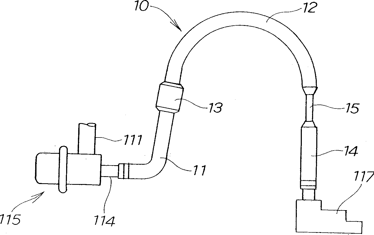
[0027] First refer to figure 1 , which shows an enlarged portion of the fuel pump assembly of the first embodiment. The illustrated fuel pump is a partial modification of the fuel pump assembly shown in Figure 5, and like parts are therefore designated by like reference numerals.

[0028] The first embodiment is characterized by its return pipe 10, which is connected to the outlet 114 of the pressure regulator 115 and the pipe end member 117, the return pipe 10 having a portion 13 of enlarged diameter placed between the plastic pipes 11, 12 Or a reduced diameter portion 15 placed between the plastic tubes 12 , 14 .

[0029] The plastic tubes 11, 12, 14 have a fixed inner diameter so that the flow rate of the fuel does not vary as it passes through them. However, the enlarged diameter portion 13 has a larger inner diameter, ie a larger cross-sectional area, so that the flow velocity is reduced. On the contrary, the ...


PUM


Abstract

A fuel pump module (102) includes a return pipe (10, 20, 30, 40) for connection between an outlet (114) of a pressure regulator (115) and a tube end component (117). The rate of flow of fuel through the return pipe is varied midway of the return pipe. This change in flow rate results in a variation in a resonant frequency, thereby preventing generation of an abnormal sound.

Description

technical field [0001] The present invention relates to a technique for preventing abnormal sound or vibration from a fuel pump. Background technique [0002] A common fuel pump assembly works on the principle shown in FIG. 5 . The fuel pump assembly 102 is attached to the fuel tank 101 at its upper end. The fuel pump assembly 102 includes a fuel pump 104 for sucking fuel through an inlet filter 103 and pressurized pumped fuel, a filter 106 connected to a fuel pump discharge pipe 115; a discharge port 113 is used to pass through All or part of the fuel of the filter 106 passes through the supply pipe 112, leading to the injector 120 as shown by arrow ①, a pressure regulator 115 with an inlet 111 branched from the filter 106, and an outlet 114 for the inlet 111 When the pressure value above exceeds a certain value, part of the fuel is returned to the fuel tank 101, and a return pipe 116 extends a predetermined length from the outlet 114; there is a pipe end member 117 at th...

Claims


Application Information

Patent Timeline
Patent Type & Authority Applications(China)
IPC IPC(8): F02M37/00F02M37/04F02M37/10F02M55/00F02M59/44
CPCF02M37/10F02M37/0052F02M37/0041F02M37/0029F02M37/0017F02M37/0058
Inventor 金子直正柳濑大树佐佐木章二宫内邦夫堀内正昭
Owner HONDA MOTOR CO LTD
Why Eureka
Try Eureka