

Device for lowering persons from high-rise building
A building and high-rise technology, applied in the direction of building rescue, life-saving equipment, etc., can solve problems such as falling, and achieve the effect of strong reliability, easy use and compact structure
- Summary
- Abstract
- Description
- Claims
- Application Information
AI Technical Summary
Problems solved by technology
Method used
Image

Examples
Embodiment Construction
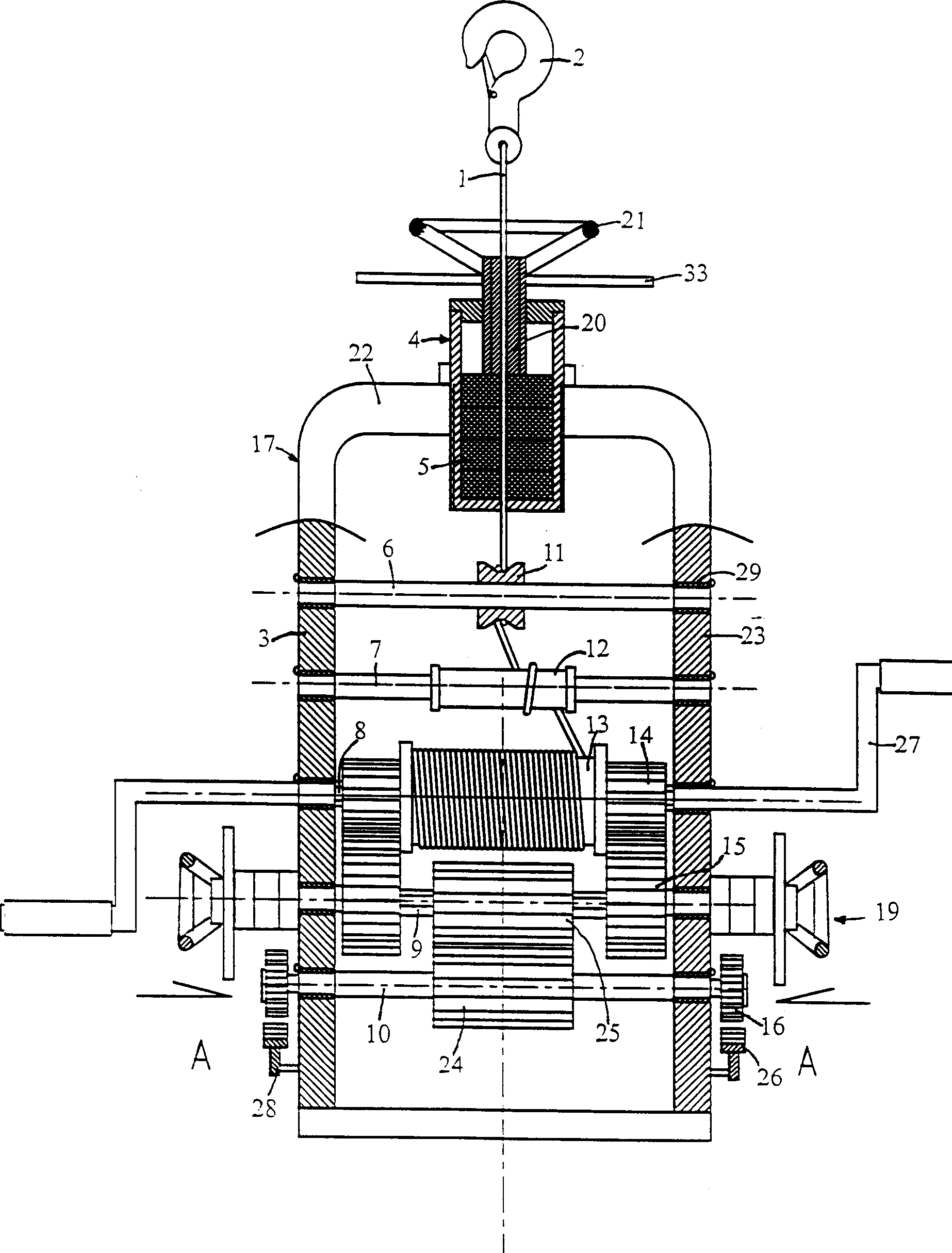
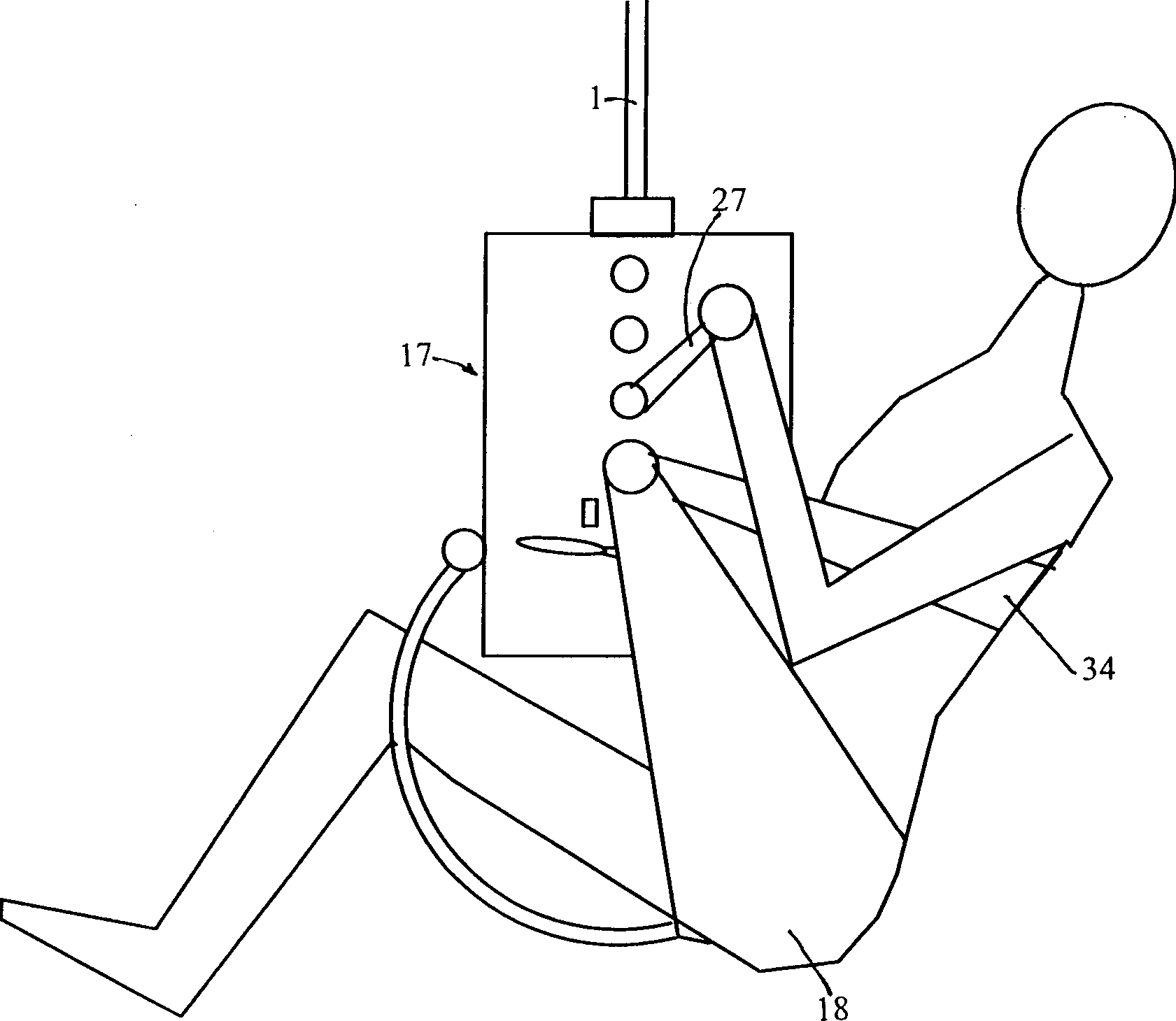
[0018] refer to figure 1 , which depicts a kind of downhill device of a high-rise building escape device, which has a traction rope 1 and a downhill device, one end of the traction rope 1 is provided with a hook 2, and the downhill device includes a frame 17, and the frame 17 includes a left vertical plate 3, Right vertical plate 23, upper horizontal plate 22, left vertical plate 3, right vertical plate 23, upper horizontal plate 22 can adopt steel plate to make, utilize bolt or welding to be assembled into frame 17, frame 17 also can be cast iron, will It is made as a one-piece structure. The packing box 4 is fixed on the central axis of the upper horizontal plate 22 by threaded connection, and can also be fixed on the central axis of the upper horizontal plate 22 by bolt connection or welding. A rubber packing 5 is installed inside the packing box 4, and a gland 20 is provided at the upper end of the packing box 4, and a running wheel 21 and a rotating rod 33 are provided a...
PUM
 Abstract
Description
Claims
Application Information