Luminous indicating plate

A technology for signs and light-emitting devices, which is applied to display devices, illuminated signs, instruments, etc., can solve the problems of insufficient uniformity of light emission and large loss of light energy, and achieve the effects of easy identification, enhanced brightness, and improved contrast

Inactive Publication Date: 2005-02-16
HONG FU JIN PRECISION IND (SHENZHEN) CO LTD +1
View PDF1 Cites 6 Cited by
  • Summary
  • Abstract
  • Description
  • Claims
  • Application Information

AI Technical Summary

Problems solved by technology

[0007] In order to overcome the problems of large loss of light energy and insufficient uniformity of light emission in the pr

Method used


Image

  • Luminous indicating plate
  • Luminous indicating plate
  • Luminous indicating plate

Examples


Embodiment Construction

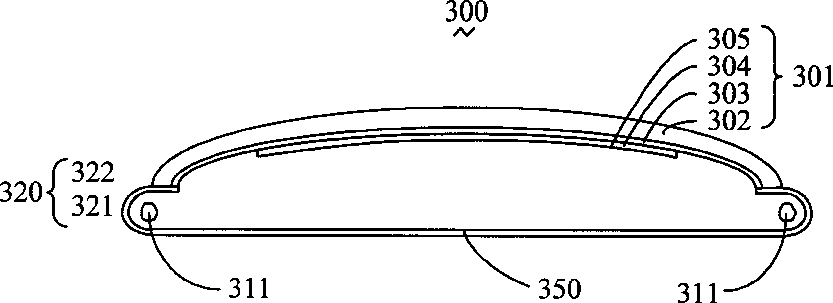
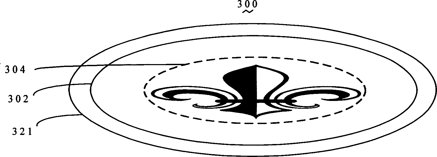
[0014] see figure 2 and image 3 , is a cross-sectional view and a top view of an embodiment of the luminous signboard of the present invention. The luminous signboard 300 includes a sign panel 301 , a light emitting device 311 and a light reflecting device 320 . The sign panel 301 may be made of soft material and attached above the reflective device 320 .

[0015] The logo panel 301 includes a transparent body 302 , a light-scattering layer 303 and a logo pattern 304 , wherein the logo pattern 304 is provided with a reflective film 305 adjacent to the light emitting device 311 .

[0016] The transparent body 302 should be made of materials with high light transmittance as far as possible, and its external shape, thickness and volume are determined according to actual needs. When the requirements are low or the scattering layer 303 is not used, it can also be processed with translucent materials. Its sides should be treated with reflective light. When using a single color,...


PUM


Abstract

The present invention relates to a luminous indicator panel, its includes a luminous device, a reflecting device and an indicator panel. Said indicator panel is supported on said reflecting device, it includes an indication pattern and a transparent body. The edge of said reflecting device is equipped with a concave receiving cavity in which the luminous device is received. Said invented luminous indicator panel can luminesce uniformly, and its optical energy loss is low.

Description

【Technical field】 [0001] The invention relates to a luminous sign board. 【Background technique】 [0002] Signs (Logos), such as billboards, car signs and traffic signs, are increasingly used in public places and businesses. Yet sign board itself can not be luminous, needs to rely on the light of reflection external lighting device to make people also can see clearly the lettering and pattern on the license plate or billboard at night. For this reason, an active light source is usually arranged on the back of the sign, and the light emitted by the light source illuminates the sign from the back, so that no external lighting device is required. Signboards with active light sources on the back are generally called luminous signboards. [0003] At present, most luminous signboards include a luminous device and markers, and the markers are illuminated by the luminous device to achieve the purpose of display. However, most of them have problems such as poor display effect. [0...

Claims


Application Information

Patent Timeline
IPC IPC(8): G09F13/00
Inventor 蔡明江李俊佑江宗韦
Owner HONG FU JIN PRECISION IND (SHENZHEN) CO LTD
Why Eureka
Try Eureka