

Pulverization generating device, dishware cleaning machine and washing machine mounting with the apparatus
A generating device and washing machine technology, which is applied to tableware washing machine/rinsing machine, other washing machines, tableware washing machine/rinsing and rinsing machine parts, etc., which can solve problems such as failure to work, oscillator failure, and fog reduction.
- Summary
- Abstract
- Description
- Claims
- Application Information
AI Technical Summary
Problems solved by technology
Method used
Image

Examples
Embodiment 1
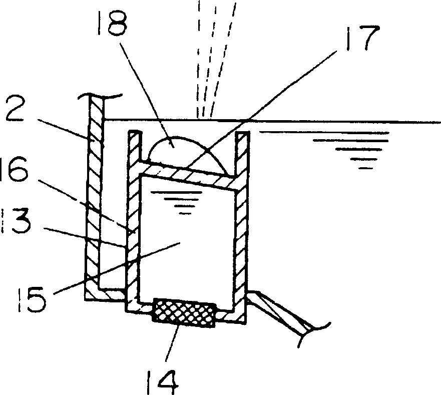
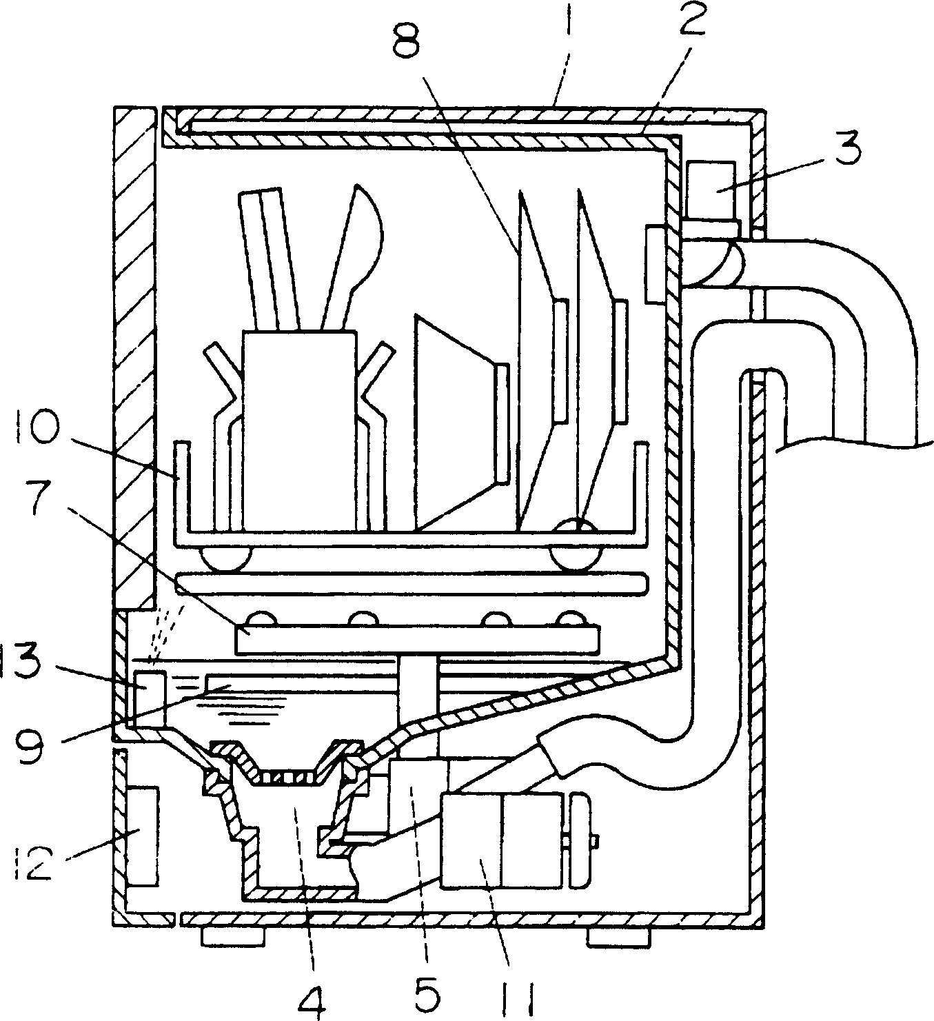
[0023] figure 2 Shows the dish washing machine in the present invention, wherein, below the front surface of the washing tank 2 is provided with an atomization generating device 13, the specific structure of the atomizing generating device 13 is as follows figure 1 shown in . exist figure 1 In the atomization generating device 13 shown in , an ultrasonic oscillator (an oscillator for generating atomization) 14 is arranged on the bottom surface, and a container 16 is arranged above the vibrating surface, and a liquid 15 is sealed in the container 16 . By enclosing the liquid 15 and the container 16, the top surface 17 facing the ultrasonic oscillator 14 in the container 16 vibrates, and then the atomized liquid (cleaning water) outside the container 16 is atomized. Among them, the enclosed liquid 15 is distilled water.
[0024] Here, the top surface 17 of the container 16 facing the ultrasonic oscillator 14 is provided in an inclined shape, and is made of resin that is ea...
Embodiment 2
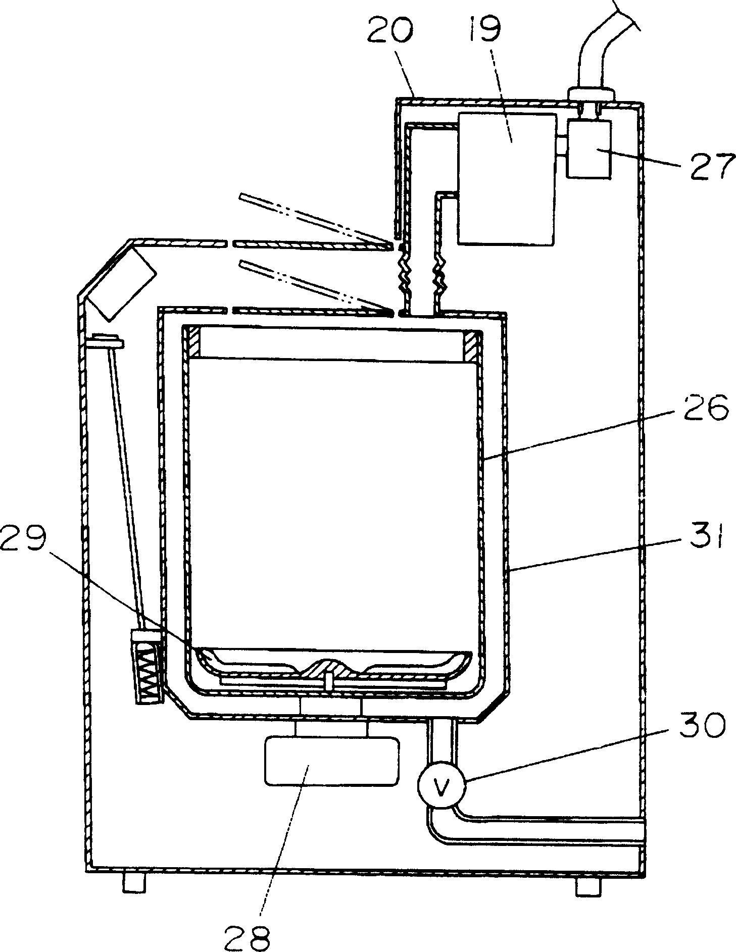
[0040] The washing machine in this embodiment is as image 3 As shown in , wherein, the inside of the washing machine body 20 is provided with an atomization generating device 19 . The specific structure of this atomization generating device 19 is as follows: Figure 4 As shown in , an ultrasonic oscillator (an oscillator for generating atomization) 21 is arranged on the bottom surface, and a container 23 is arranged on the upper side of the vibrating surface of the ultrasonic oscillator 21, and a liquid 22 is sealed in the container 23. Through the liquid 22 and the container 23, the vibrating top surface 24 of the ultrasonic oscillator 21 facing the container 23 vibrates, so that the liquid to be atomized (washing water) outside the container 23 is atomized.
[0041] In addition, the detergent input chamber 25 for inputting detergent (or washing powder) is arranged above the top surface 24 facing the ultrasonic oscillator 21 . The top surface 24 facing the ultrasonic oscil...
PUM
 Abstract
Description
Claims
Application Information