Gas injection port structure of flat fluorescent lamp

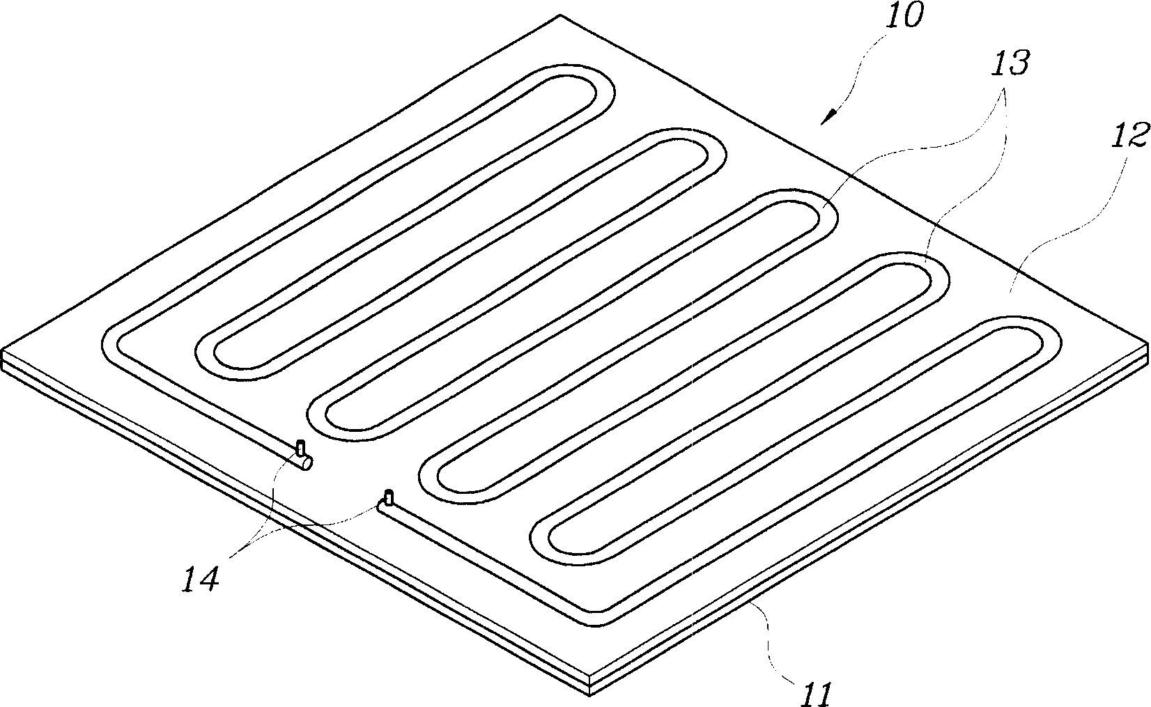
一种充气口、荧光灯的技术,应用在电管/灯排气、电管/灯填充、放电管/灯的制造等方向,能够解决难玻管23充入惰性气体、平面荧光灯FFL20难制造、降低效率等问题

Active Publication Date: 2006-03-29
GUANGZHOU GENFENG TECH DEV CO LTD +1
View PDF0 Cites 0 Cited by
  • Summary
  • Abstract
  • Description
  • Claims
  • Application Information

AI Technical Summary

Problems solved by technology

Therefore, the problem of the flat fluorescent lamp FFL 20 is that the flat fluorescent lamp FFL 20 is difficult to manufacture
In addition, the complex structure of the gas filling port 24 makes it difficult to fill the glass tube 23 with inert gas, which reduces the efficiency of this process.

Method used


Image

  • Gas injection port structure of flat fluorescent lamp
  • Gas injection port structure of flat fluorescent lamp
  • Gas injection port structure of flat fluorescent lamp

Examples


Embodiment Construction

[0027] Preferred embodiments of the present invention will now be described in detail with reference to the accompanying drawings. Wherever possible, the same parts have been designated by the same or like reference numerals throughout the drawings.

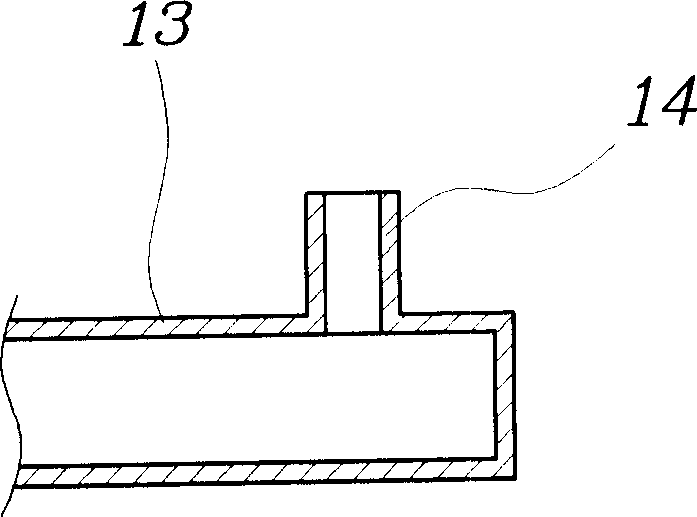
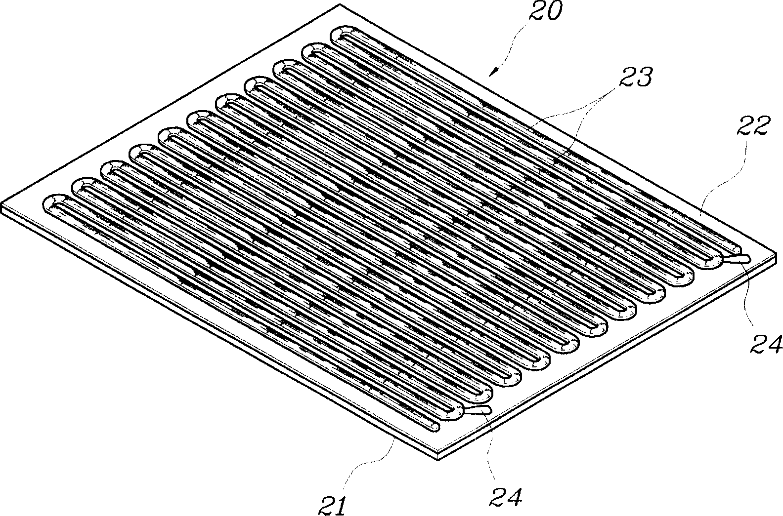
[0028] Figure 6 is a perspective view of the structure of the flat fluorescent lamp FFL according to the first embodiment of the present invention. Figure 7 yes Figure 6 A cross-sectional view of the gas filling port of the flat fluorescent lamp FFL shown in .

[0029]As shown in the figure, according to the gas filling port structure of the flat fluorescent lamp FFL 20 according to the first embodiment of the present invention, only one gas filling port 40 is formed at a predetermined position on the upper plate 22 . Specifically, the gas charging port 40 is formed on the upper plate 22 at a position outside the protruding glass tube 23 , thus allowing the gas charging port 40 to communicate with the inner space S of the g...


PUM


Abstract

The structure has a gas injection port (40) formed as horizontal port that lies on an upper plate (22) of a flat fluorescent lamp at a preset position such that the injection port is lower than a height of a protruding channel of the upper plate. The upper plate is integrated with a lower plate to form a single body. The gas injection port includes a mercury getter and sealing material.

Description

technical field [0001] The present invention generally relates to a flat fluorescent lamp FFL applied to a backlight of a display such as an LCD, and more particularly, the present invention relates to a gas filling port structure of a flat fluorescent lamp FFL, which is formed as a gas filling port of a flat fluorescent lamp FFL and is arranged on a flat fluorescent lamp The height of the protruding glass tubes on the upper plate of the FFL is equal to or lower than the height of the protruding glass tubes, so that the flat fluorescent lamp FFL is the thinnest, which conforms to the current development trend of thinning FFL displays including flat fluorescent lamps. Background technique [0002] Generally, in order to manufacture a flat fluorescent lamp, firstly, glass is properly processed at a high temperature to form a hollow glass body having a specific shape. In the second step, the air in the hollow glass body is evacuated through the air filling port to reduce the pr...

Claims


Application Information

Patent Timeline
Patent Type & Authority Applications(China)
IPC IPC(8): H01J9/24H01J9/385H01J9/395H01J61/30H01J61/26
CPCH01J61/307H01J9/38H01J31/15
Inventor 尹载斗
Owner GUANGZHOU GENFENG TECH DEV CO LTD
Why Eureka
Try Eureka