Small form-factor pluggable transceiver

a plug-in transceiver, small technology, applied in the direction of line-transmission details, baseband system details, coupling device connections, etc., can solve the problem of unfavorable conventional sfp transceiver, and achieve the effect of convenient observation

Active Publication Date: 2019-01-29
AXCEN PHOTONICS CORP
View PDF10 Cites 1 Cited by
  • Summary
  • Abstract
  • Description
  • Claims
  • Application Information

AI Technical Summary

Benefits of technology

[0005]In summary, the unlocking member of the SFP transceiver of the present disclosure can be rotated relative to the housing so that the engagement or d

Problems solved by technology

However, the conventional SFP transceiver is not convenient because the engagement and the disengagement between the conventi

Method used


Image

  • Small form-factor pluggable transceiver
  • Small form-factor pluggable transceiver
  • Small form-factor pluggable transceiver

Examples


first embodiment

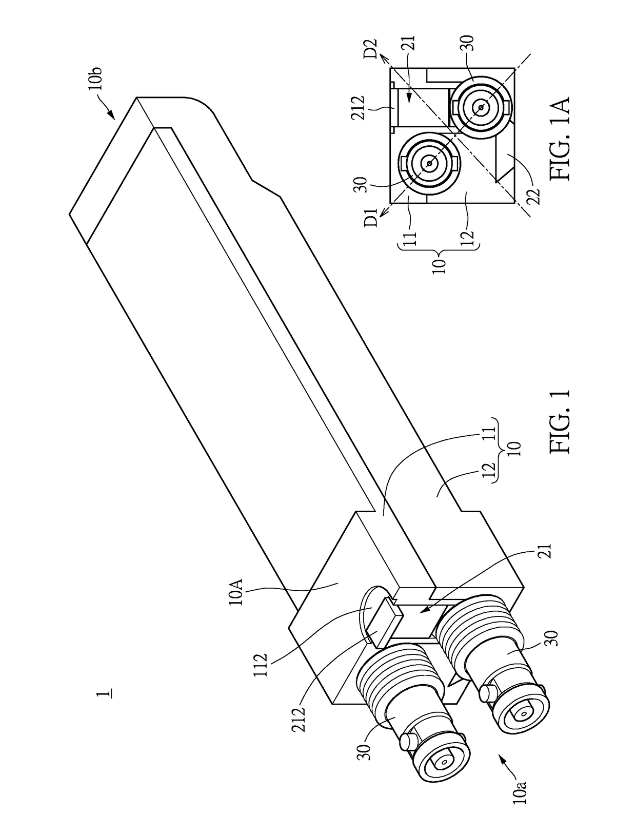
[0020]Reference is made to FIGS. 1 to 5, which illustrate a first embodiment of the present disclosure. The present embodiment discloses a small form-factor pluggable (SFP) transceiver 1, which can be electrically connected to two electrical signal wires and inserted into an electrical connection slot of an electronic apparatus, e.g., a switch or a router so that electrical signals from the two electrical signal wires can be converted by the SFP transceiver 1, and then be transmitted to the electronic apparatus through the SFP transceiver 1.

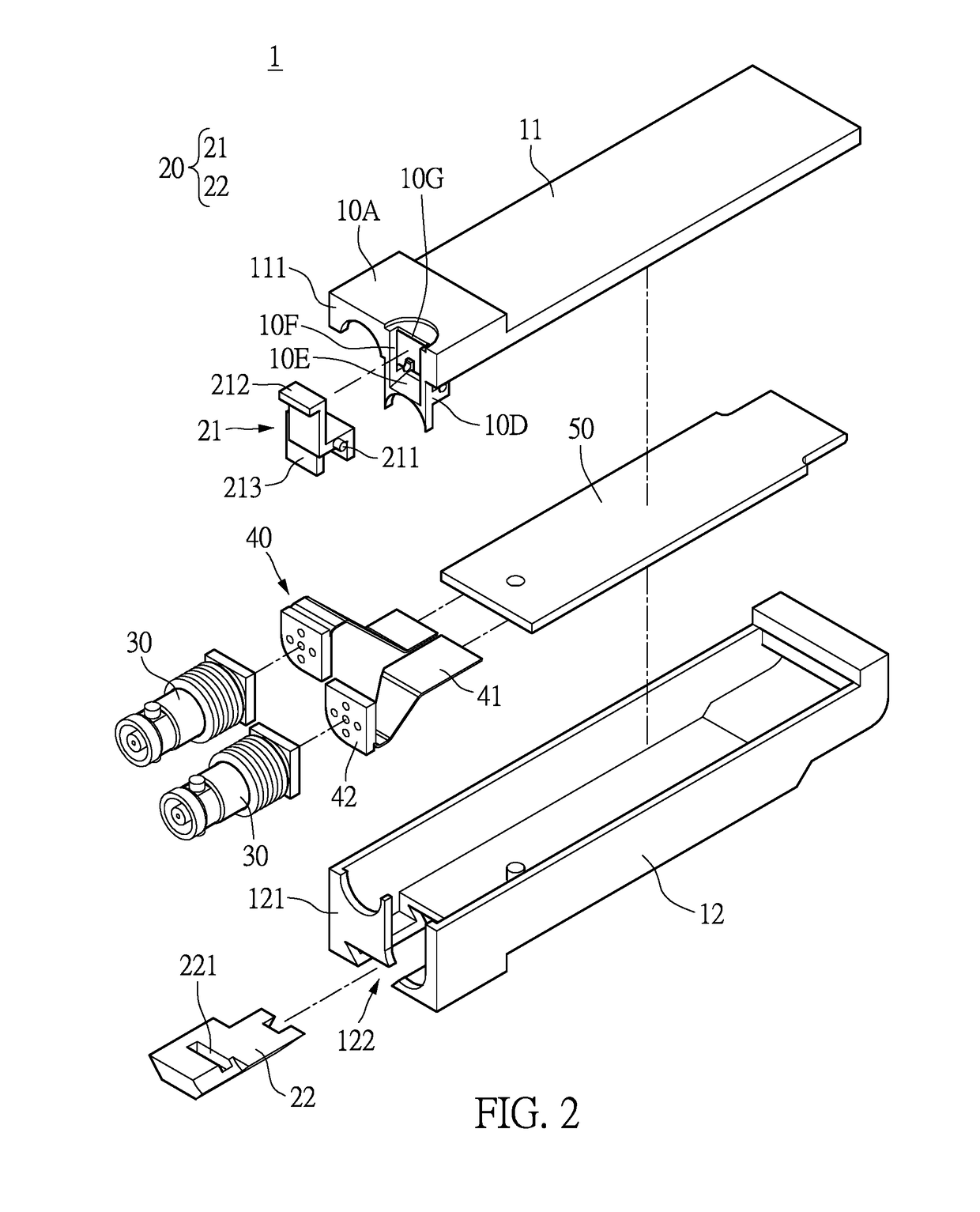
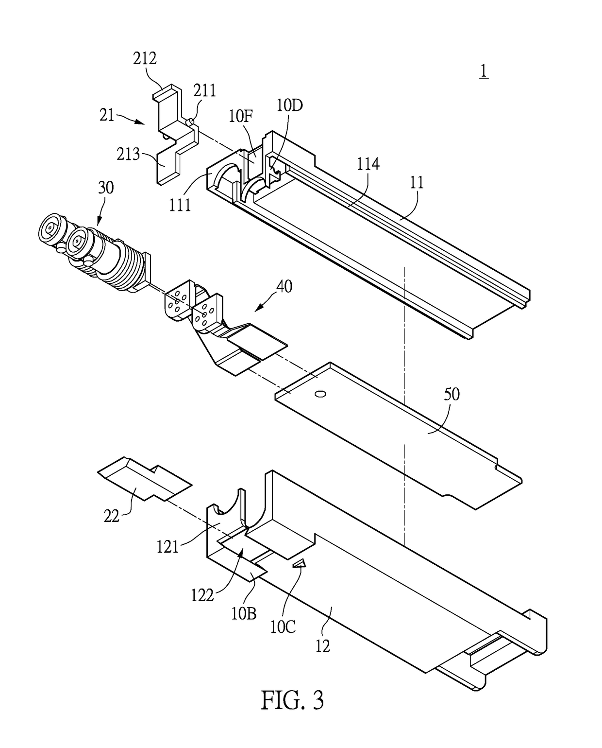
[0021]As shown in FIGS. 1 to 3, the SFP transceiver 1 includes a housing 10, an unlocking assembly 20, two electrical signal connectors 30, two flexible assemblies 40, and a circuit board 50. The housing 10 includes an upper cover 11 and a lower cover 12. The upper cover 11 and the lower cover 12 in the present embodiment are connected to each other so as to form the housing 10 defining an accommodating space SP therein, as shown in FIG. 4. The t...

second embodiment

[0032]Reference is made to FIGS. 6 to 9, which illustrate the SFP transceiver 1′ according to a second embodiment of the present disclosure. The SFP transceiver 1′ in the present embodiment includes a housing 10, an unlocking assembly 20, two electrical signal connectors 30, two flexible assemblies 40, and a circuit board 50. The following description discloses the difference between the present embodiment and the first embodiment.

[0033]In the present embodiment, the housing 10 is formed by assembling an upper cover 11, a lower cover 12, and a front plate 13 together, in which the front plate 13 is at the front end 10a of the housing 10. The upper cover 11, the lower cover 12, and the front plate 13 are three independent components, and the connection mechanisms therebetween can be determined respectively according to design requirements.

[0034]As shown in FIGS. 8 and 9, the front plate 13 includes a plastic layer 131 and a metallic layer 132, which respectively define two opposite m...

third embodiment

[0041]Reference is made to FIGS. 11 and 12, which illustrate the SFP transceiver 1″ according to a third embodiment of the present disclosure. The SFP transceiver 1″ in the present embodiment includes a housing 10, an unlocking assembly 20, two electrical signal connectors 30, two flexible assemblies 40, and a circuit board 50. The housing 10 in the present embodiment includes an upper cover 11, a lower cover 12, and a front plate 13′. The following description discloses the difference between the present embodiment and the first and second embodiments.

[0042]In the present embodiment, when the upper cover 11, the lower cover 12, and the front plate 13′ are assembled together, an outer surface of the front plate 13′ is coplanar with an end portion of the upper cover 11 and the lower cover 12, which are arranged around the outer surface of the front plate 13′. The front plate 13′ of the present embodiment is substantially identical to that of the second embodiment. For example, the fr...


PUM


Abstract

A small form-factor pluggable (SFP) transceiver is provided for being inserted into an electrical connection slot of an electronic apparatus. The SFP transceiver includes a housing, two electrical signal connectors disposed a front end of the housing, and an unlocking assembly having an unlocking member and an interlock member. The housing includes an engaging portion disposed on a bottom surface thereof and configured to be engaged with the electrical connection slot, thereby firmly fastening the SFP transceiver into the electrical connection slot. The unlocking member has a manipulating portion exposed at the front end and arranged adjacent to a top surface of the housing. The interlock member is movably disposed on the housing. When the manipulating portion is rotated in a direction away from the front end and the top surface, the unlocking member moves the interlock member to separate the engaging portion from the electrical connection slot.

Description

BACKGROUND OF THE INVENTION1. Field of the Invention[0001]The present disclosure relates to a pluggable transceiver; in particular, to a small form-factor pluggable (SFP) transceiver.2. Description of Related Art[0002]Conventional SFP transceiver is inserted into an electrical connection slot of an electronic apparatus and engaged therewith. If a user wants to separate the conventional SFP transceiver from the electrical connection slot, the engagement between the conventional SFP transceiver and the electrical connection slot can be released by using an unlocking member of the conventional SFP transceiver. However, the conventional SFP transceiver is not convenient because the engagement and the disengagement between the conventional SFP transceiver and the electrical connection slot cannot be directly observed outside the conventional SFP transceiver.SUMMARY OF THE INVENTION[0003]The present disclosure provides a small form-factor pluggable (SFP) transceiver to solve the drawbacks...

Claims


Application Information

Patent Timeline
IPC IPC(8): H04B1/38H01R13/633H04B3/02H04L25/02H04B1/40H01R13/627
CPCH04B1/40H01R13/6272H04B3/02H04L25/0298H01R13/6335H04B1/38
Inventor CHEN, YI-MING
Owner AXCEN PHOTONICS CORP
Why Eureka
Try Eureka