Colorimetric device and printing apparatus
a colorimetric device and printing apparatus technology, applied in the direction of optical radiation measurement, instruments, spectrometry/spectrophotometry/monochromators, etc., can solve the problem of colorimetric devices becoming larger in siz
- Summary
- Abstract
- Description
- Claims
- Application Information
AI Technical Summary
Benefits of technology
Problems solved by technology
Method used
Image

Examples
first embodiment
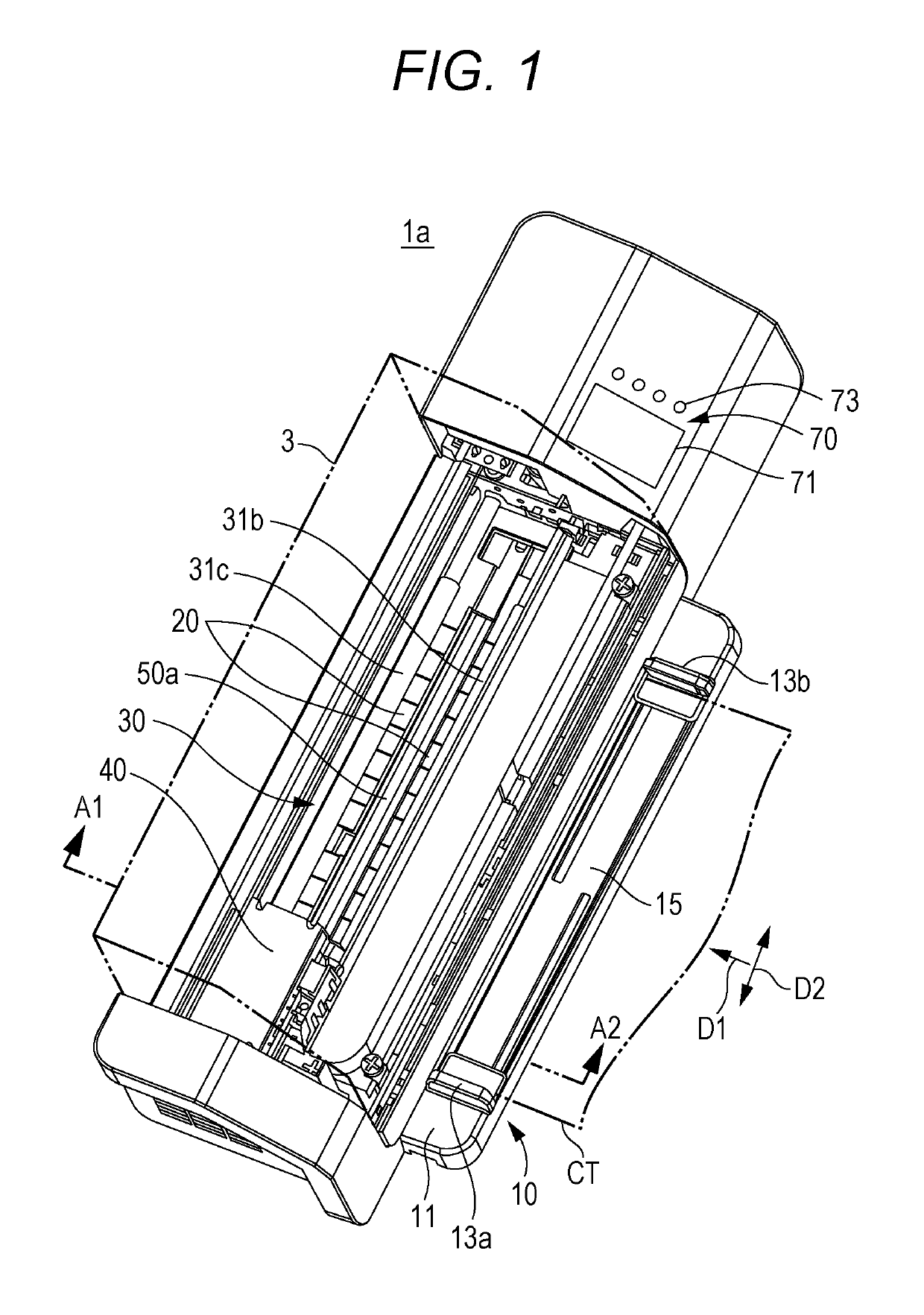
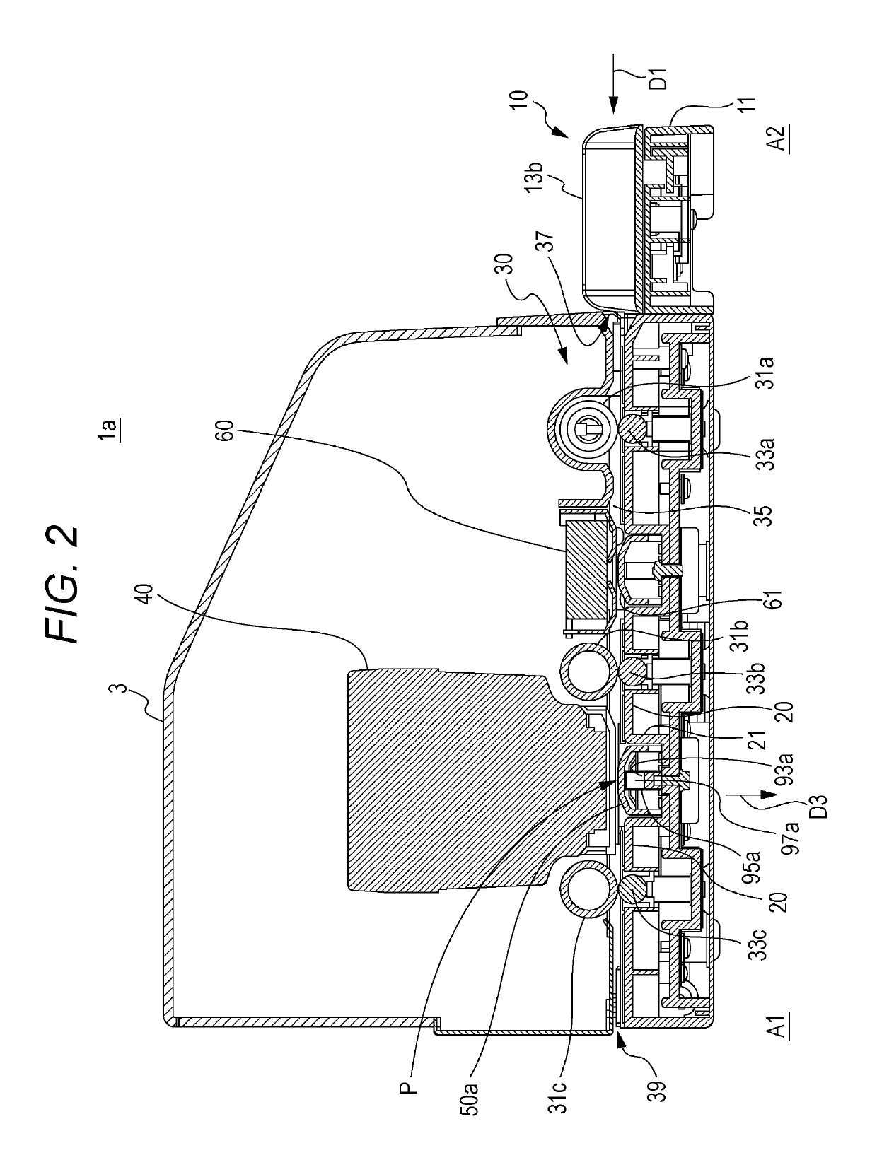
[0040]FIG. 1 is a perspective view of an external appearance of a colorimetric device 1a according to the present invention. FIG. 2 is a cross-sectional view of the colorimetric device 1a illustrated in FIG. 1, which is taken along a line A1-A2. FIG. 1 illustrates the colorimetric device 1a from which an exterior cover 3 has been detached, and FIG. 2 illustrates the colorimetric device 1a to which the exterior cover 3 has been attached.
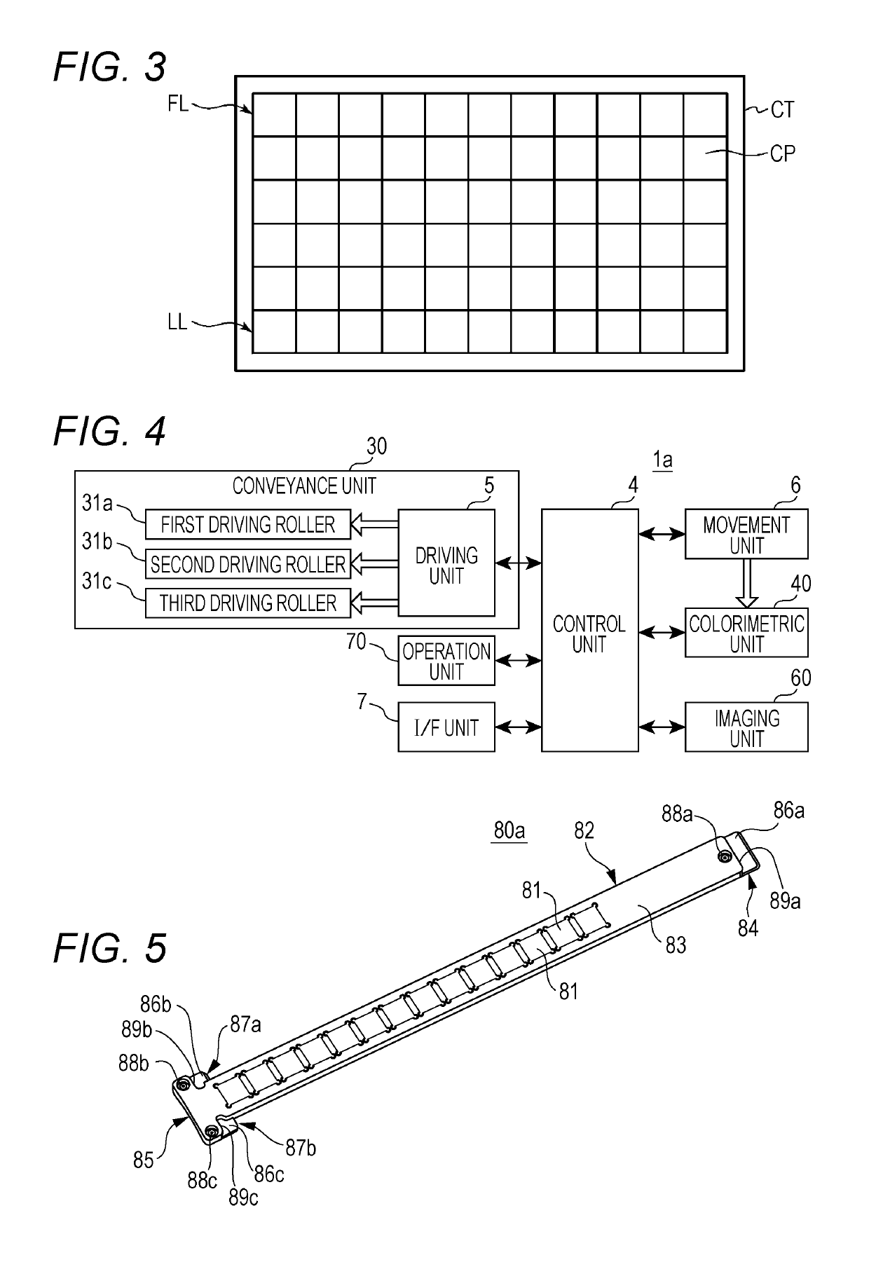
[0041]The colorimetric device 1a includes a sheet feeding unit 10, a conveyance unit 30, a colorimetric unit 40, a backing member 50a, an imaging unit 60, an operation unit 70, and the exterior cover 3. As an example of a predetermined sheet to be subjected to the colorimetry, a color chart CT is described. FIG. 3 is a plan view illustrating one example of the color chart CT. The color chart CT is a sheet of paper on which a plurality of color patches CP with various hues, brightness, and chroma is printed. A plurality of color patches CP with a recta...
second embodiment
[0109]Note that the tiles included in each of the color tile member 80b1 and 80b2 may be made different in accordance with the purpose of examining the accuracy of the colorimetric device 1b (FIG. 11) according to the For example, the color tile member 80b1 includes a white tile, a plurality of gray tiles with different gray densities, and a black tile, which are used to examine the intensity of the light received by the colorimetric unit 40. On the other hand, the color tile member 80b2 includes a plurality of tiles with different colors and high chroma, which are used to examine the wavelength of the light received by the colorimetric unit 40.
[0110]The color tile member 80b contains fewer color tiles 81 than the color tile member 80a illustrated in FIG. 5, so that the color tile member 80b is shorter than the color tile member 80a.
[0111]The structure of the color tile member 80b is the same as that of the color tile member 80a except the aforementioned point.
[0112]FIG. 11 is a p...
third embodiment
[0119]FIG. 13 is a perspective view of an external appearance of the colorimetric device 1c to which the color tile member is attached. FIG. 13 is different from FIG. 11 in that the two color tile members 80c are arranged on the backing member 50a instead of the color tile member 80b in the longitudinal direction of the backing member 50a.
[0120]The color tile member 80c1 is held by holders 23d, 23e, 23f, and 23g corresponding to a part of the base member 20. The color tile member 80c2 is held by holders 23h, 23i, 23j, and 23k corresponding to a part of the base member 20.
[0121]The place where the color tile member 80c2 is disposed on the backing member 50a is the central part of the backing member 50a and is not the end side. Thus, the color tile member 80c2 is not held at three points but by four points. If the color tile member 80c1 and the color tile member 80c2 have the same structure, the manufacturing cost for the color tile members 80c1 and 80c2 can be reduced. Therefore, t...
PUM
| Property | Measurement | Unit |
|---|---|---|
| color | aaaaa | aaaaa |
| height | aaaaa | aaaaa |
| colorimetric device | aaaaa | aaaaa |
Abstract
Description
Claims
Application Information
 - R&D
- Intellectual Property
- Life Sciences
- Materials
- Tech Scout
- Unparalleled Data Quality
- Higher Quality Content
- 60% Fewer Hallucinations
Browse by: Latest US Patents, China's latest patents, Technical Efficacy Thesaurus, Application Domain, Technology Topic, Popular Technical Reports.
© 2025 PatSnap. All rights reserved.Legal|Privacy policy|Modern Slavery Act Transparency Statement|Sitemap|About US| Contact US: help@patsnap.com