Stopping point

a technology of stopping point and attachment point, which is applied in the direction of swinging, fastening means, load-engaging elements, etc., can solve the problem of unsatisfactory second known solution, and achieve the effect of convenient installation

Inactive Publication Date: 2005-01-27
RUD KETTENFABRIK RIEGER & DIETZ GMBH & CO
View PDF29 Cites 3 Cited by
  • Summary
  • Abstract
  • Description
  • Claims
  • Application Information

AI Technical Summary

Benefits of technology

[0005] It is not just the case that the already indicated disadvantages of the known design described above are eliminated in the case of the point of attachment according to the invention; in addition, the arrangement of the rolling-contact bearings proves to be extremely easy to install since there is no need for the rolling-contact bodies to be supplied by way of special supply channels.

Problems solved by technology

This second known solution is not fully satisfactory because, with it, the distance between the connection eye and the load is comparatively large and, in the case of forces acting more or less obliquely on the connection eye, the tilting resistance of the connection eye leaves something to be desired.

Method used


Image

  • Stopping point
  • Stopping point

Examples


Embodiment Construction

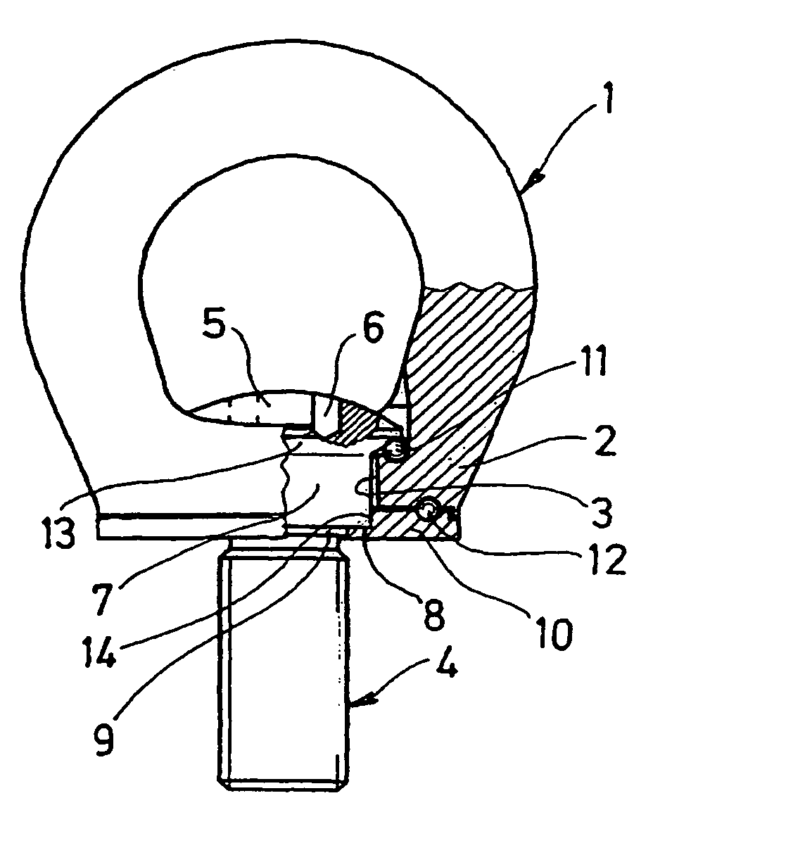
[0004] The object of the invention, in the case of a point of attachment of the generic type, is for the rotatability of the connection eye to be ensured even when heavy loads are handled. Attempts are made simultaneously for the connection-eye tilting resistance, which is already high in any case on account of the proximity of the base of the connection eye to the load, to be increased further, in the case of forces being introduced obliquely, by a particularly expedient arrangement and selection of the rolling-contact bearings. This object is achieved according to the invention in that, in the case of a point of attachment of the generic type, a supporting disk is connected in captive fashion to the anchoring bolt, and in that the base of the connection eye is supported, via a first series of rolling-contact bodies, against the annular flange of the head and, via a second series of rolling-contact bodies, against the supporting disk.

[0005] It is not just the case that the already...


PUM


Abstract

Disclosed is a stopping point comprising a connecting eye (1) used with stopping or lashing means. Said connecting eye is rotatably mounted on an anchoring screw (4) which is undetachably connected to a supporting disc (10). The base (2) of the connecting eye leans against a ring flange (13) of the anchoring screw (4) head (5) via a first series of rolling bodies (11) and against the supporting disc (10) via a second series of rolling bodies (12) so as to ensure high rotatability of the connecting eye (1) in relation to the anchoring screw (4).

Description

TECHNICAL FIELD [0001] The invention relates to a point of attachment having a connection eye, into which an attachment or lashing means can be fitted, and an anchoring bolt, which serves for fastening the same on an object and of which the head is provided with an annular flange on which is supported the connection eye, which has a base provided with a bore and is mounted in a rotatable manner on the anchoring bolt. PRIOR ART [0002] A point of attachment of the abovementioned type which is designed as a so-called ring bolt is known from EP 0654611 B1. In the case of the known point of attachment, a cylindrical section which adjoins the annular flange of the head of the anchoring bolt projects slightly beyond the underside of the base of the connection eye, with the result that the latter can rotate freely about the longitudinal axis of the anchoring bolt. The known solution is distinguished by a simplicity which takes account of the mass-produced nature of points of attachment. As ...

Claims


Application Information

Patent Timeline
Patent Type & Authority Applications(United States)
IPC IPC(8): B66C1/66F16G15/08
CPCF16G15/08B66C1/66
Inventor SMETZ, REINHARD
Owner RUD KETTENFABRIK RIEGER & DIETZ GMBH & CO
Why Eureka
Try Eureka