Knee protection airbag device

a technology for airbags and knees, applied in the direction of pedestrian/occupant safety arrangements, vehicular safety arrangements, vehicle components, etc., can solve the problems of airbag cover gap, increase in weight of the case, and further weight of the entire airbag device, and achieve the effect of reducing weigh

a technology for airbags and knees, applied in the direction of pedestrian/occupant safety arrangements, vehicular safety arrangements, vehicle components, etc., can solve the problems of airbag cover gap, increase in weight of the case, and further weight of the entire airbag device, and achieve the effect of reducing weigh

US20050073134A1Active Publication Date: 2005-04-07TOYODA GOSEI CO LTD

Image

  • Knee protection airbag device
  • Knee protection airbag device
  • Knee protection airbag device

Examples


Embodiment Construction

[0035] An embodiment of the present invention is described below with reference to the accompanying drawings. In addition, the invention is not limited to the embodiment. All modifications within the requirements of the claims and equivalents with respect to the requirements should be included in the scope of the claims.

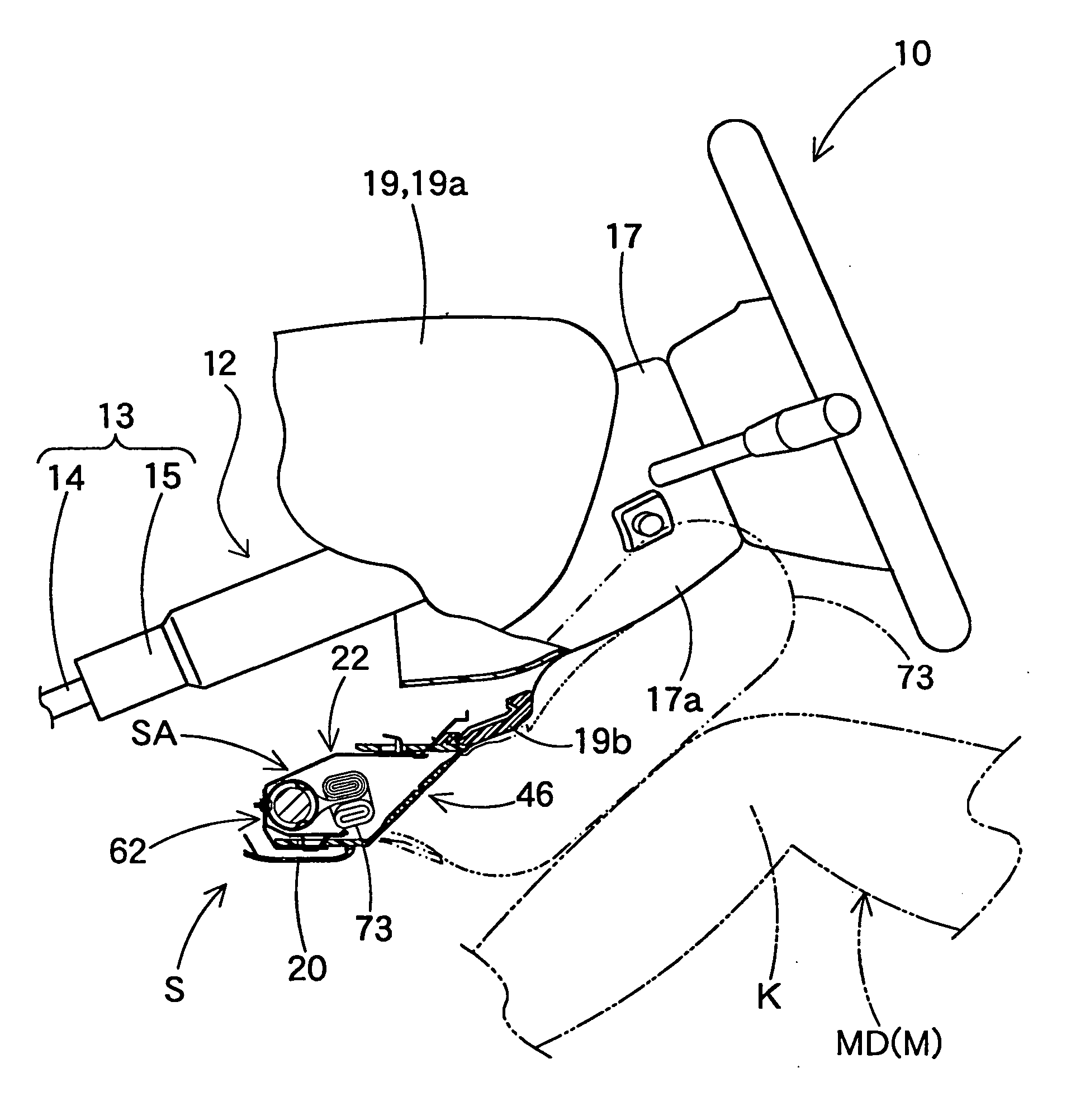
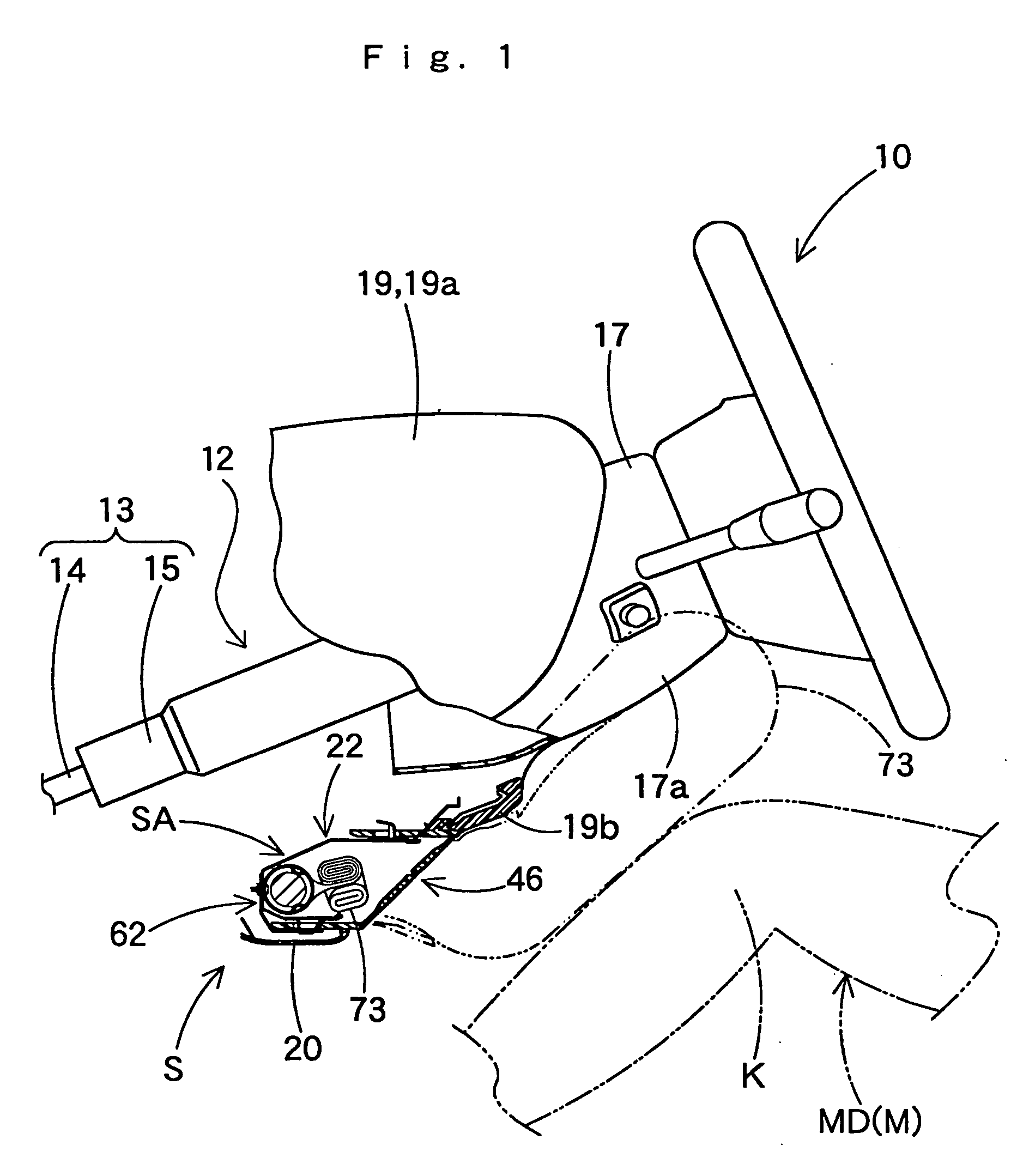
[0036] As shown in FIGS. 1 and 6, the knee protection airbag device S of the embodiment is arranged below the steering column 12 in front of a driver MD as an occupant M for protecting the knees K of the driver MD.

[0037] Here, up-down, left-right, and front-rear in this specification correspond to the up-down, left-right, and front-rear of the vehicle as the knee protection airbag device S is mounted on the vehicle.

[0038] As shown in FIG. 1, the steering column 12 includes a column body 13 connected to the steering wheel 10, and a column cover 17 covering the column body 13 at the lower side of the steering wheel 10. The column body 13 includes a main shaft 14 and...


PUM


Abstract

In the knee protection airbag device of the present invention, an airbag folded and housed in a case opened rearward of the vehicle pushes open the door portion of an airbag cover assembled with the case, upon inflow of inflation gas from the inflator. Around the airbag cover, there is arranged an interior decoration member for vehicle which is provided separate from the airbag cover. The door portion includes at least an upper door openable upward. The upper door is formed in such a size as to cover a gap formed between the interior decoration member and the airbag cover when opened upon deployment of the airbag.

Description

[0001] The present application claims priority to Japanese Patent Application of Matsuura et al., filed Jul. 18, 2002, under No. 2002-209969, its entirety is hereby incorporated into the present application by this reference. BACKGROUND OF THE INVENTION [0002] 1. Field of the Invention [0003] The present invention relates to a knee protection airbag device which protects the knees of a seated vehicle occupant with an airbag expanding and inflating by admitting inflation gas. [0004] 2. Description of Related Art [0005] In the prior art, Japanese Patent Laid-Open No. Hei 9-123863 shows a device for protecting the knees of a vehicle occupant. This prior art illustrates a device located below the column cover to protect the knees of a driver with an expanding and inflating airbag. This device includes a case opened rearward for housing the folded airbag, and an airbag cover covering the case opening and including a door portion openable upon airbag deployment. The airbag cover is assemb...

Claims


Application Information

Patent Timeline
07 Apr 2005
Publication
US20050073134A1
IPC
B60R21/16; B60R21/20; B60R21/206
CPC
B60R21/206; B60R2021/23169; B60R21/231
Inventors
MATSUURA, HIROKAZU; NAGATA, ATSUSHI