Connector

a technology of connecting rods and retainers, which is applied in the direction of connection, electrical apparatus, coupling device connection, etc., can solve the problems of insufficient strength of housing and retainer, and similar problems, and achieve the effect of sufficient strength and simplified insertion of retainer into the insertion hole of the housing

Active Publication Date: 2006-03-02
KK TOKAI RIKA DENKI SEISAKUSHO
View PDF6 Cites 14 Cited by
  • Summary
  • Abstract
  • Description
  • Claims
  • Application Information

AI Technical Summary

Benefits of technology

[0021] Thus, as well as the insertion of the retainer into the insertion hole of the housing being simplified, the engagement pawls of the retainer reliably engage with the provisional anchoring pieces and the main anchoring pieces of the housing.
[0022] At a connector relating to the present invention as described above, it is possible to couple a housing with a retainer with sufficient strength, even with a reduction in scale.

Problems solved by technology

Accordingly, there has been a disadvantage in that the housing and the retainer could not be joined with sufficient strength.
Furthermore, this problem has similarly arisen with the provisional anchoring pieces of the housing and the provisional anchorage pawls of the retainer.

Method used


Image

  • Connector
  • Connector
  • Connector

Examples


Embodiment Construction

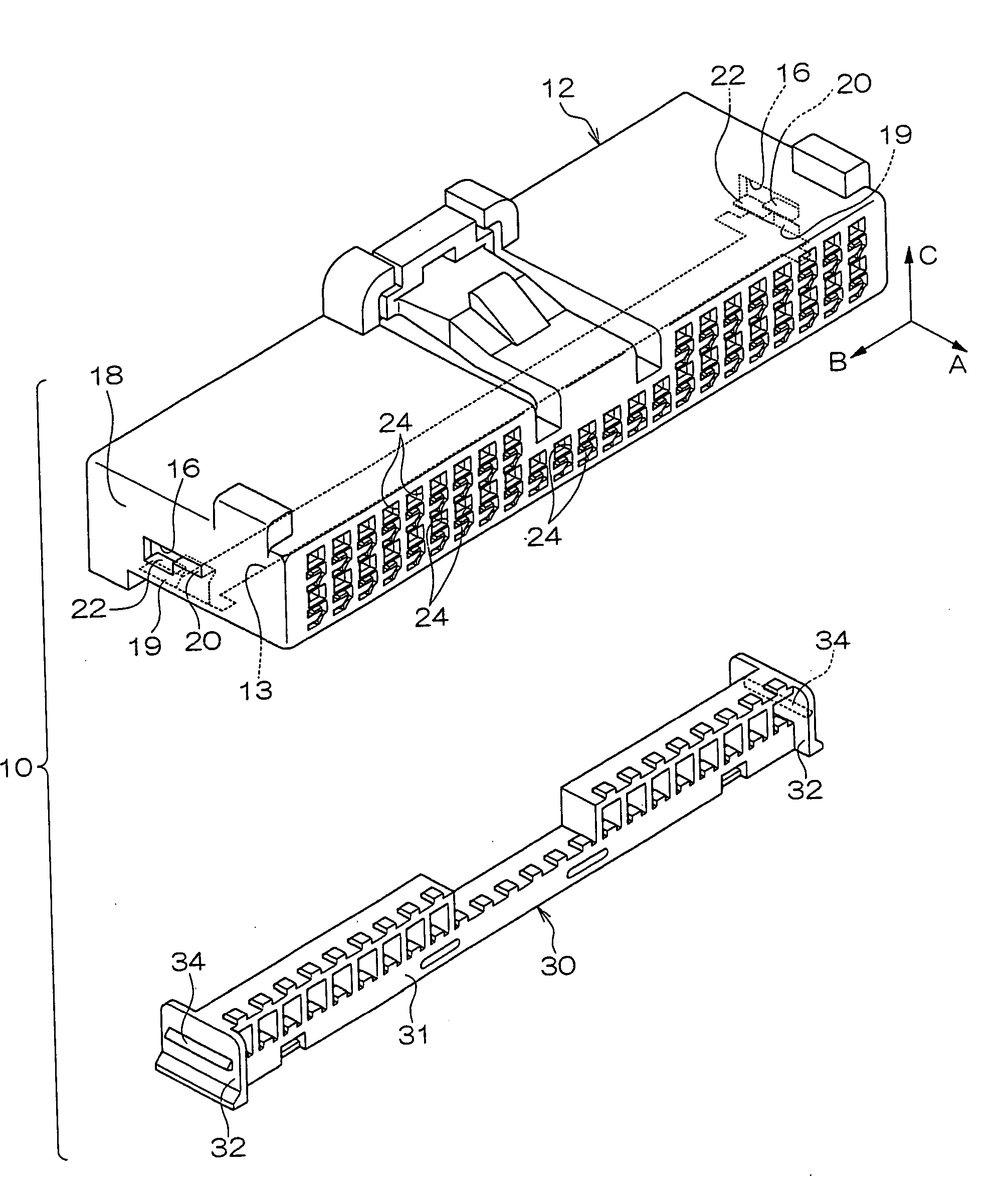
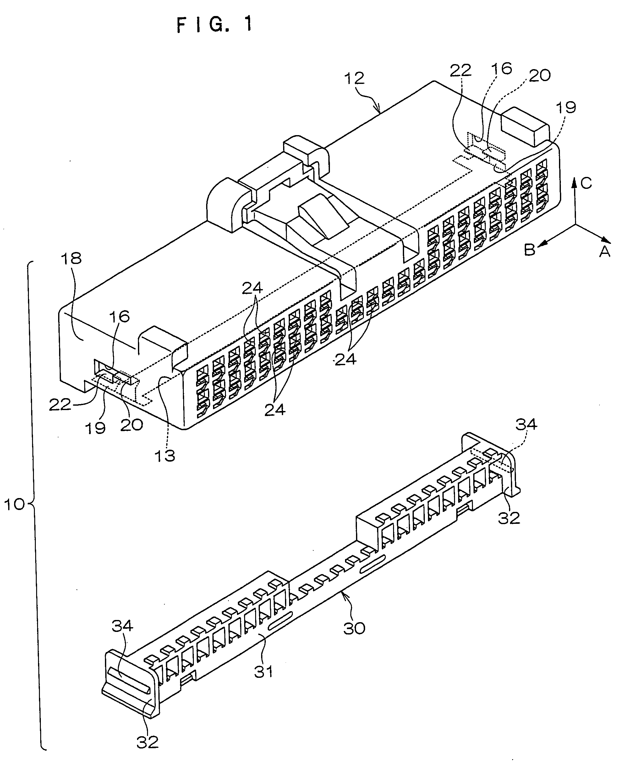
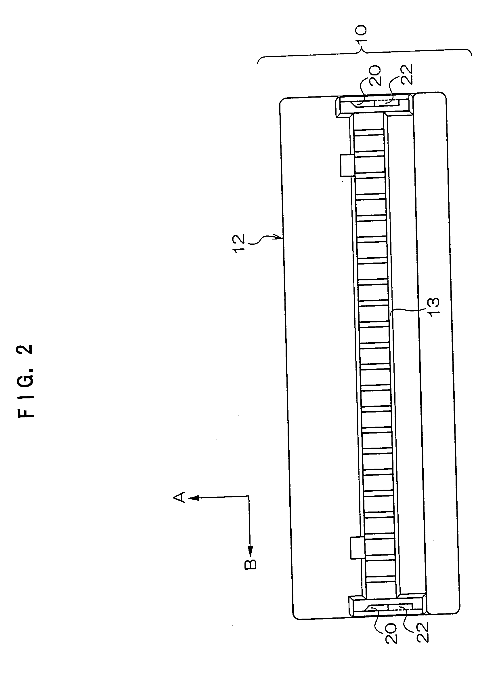
[0031] A connector 10 relating to an embodiment of the present invention will be described. Hereafter, for convenience of description, a direction which is shown by an arrow A where appropriate in the drawings is referred to as rearward, a direction shown by an arrow B, which intersects arrow A, is referred to as leftward, and a direction shown by an arrow C, which intersects arrow A and arrow B, is referred to as upward. FIG. 1 shows an exploded perspective view of the connector 10, and FIG. 2 shows a bottom view of a housing 12 of the connector 10. Further, FIG. 3 shows a right side view of the connector 10 according to FIG. 1, and FIG. 4 shows a cross-sectional view of the connector 10, cut along line 4-4 of FIG. 3.

[0032] As shown in FIG. 1, the connector 10 is provided with the housing 12 and a retainer 30. The housing 12 of the connector 10 is constituted of a resin material and is formed in a substantially rectangular box shape. Terminal insertion holes 24, for insertion of u...


PUM


Abstract

A connector in which a housing and a retainer are coupled with sufficient strength when the connector is reduced in scale. In this connector, provisional anchoring pieces and main anchoring pieces are provided at two end portions of an inner peripheral wall of an insertion hole formed in the housing, with lengths along a direction that intersects a direction of insertion of the retainer into the insertion hole. At outer sides of two end portions of the retainer, anchorage pawls, which are formed to be engageable with the main anchoring pieces and the provisional anchoring pieces, are provided with lengths along the intersecting direction. With this structure, when the retainer is inserted into the insertion hole of the housing, the anchorage pawls engage, at two end portions of the connector, with the provisional anchoring pieces and with the main anchoring pieces.

Description

CROSS-REFERENCE TO RELATED APPLICATION [0001] This application claims priority under 35 USC 119 from Japanese Patent Application No. 2004-256078, the disclosure of which is incorporated by reference herein. BACKGROUND OF THE INVENTION [0002] 1. Field of the Invention [0003] The present invention relates to a connector suitable for, for example, connections of wire harnesses used in vehicles and the like. [0004] 2. Description of the Related Art [0005] Connectors are employed for connections of, for example, wire harnesses used in vehicles and suchlike. More specifically, among such connectors, there are connectors which are provided with housings and retainers, one example of which has been disclosed in Japanese Patent Application Laid-Open (JP-A) No. 9-17484. [0006] In this type of connector, a housing is formed in, for example, a substantially rectangular box shape, at one face of which (for example, a rear face) terminal insertion holes are plurally formed in an array, for insert...

Claims


Application Information

Patent Timeline
Patent Type & Authority Applications(United States)
IPC IPC(8): H01R13/514
CPCH01R13/4362
Inventor OKAMOTO, REIKISASAKI, HAREHIDEKATO, YOSHIAKI
Owner KK TOKAI RIKA DENKI SEISAKUSHO
Why Eureka
Try Eureka