System for providing power over Ethernet through a patch panel

a patch panel and patch panel technology, applied in the field of power over ethernet, can solve the problems of wasteful rack space and less than optimal installation

Inactive Publication Date: 2006-03-23
CISCO TECH INC
View PDF6 Cites 80 Cited by
  • Summary
  • Abstract
  • Description
  • Claims
  • Application Information

AI Technical Summary

Benefits of technology

[0031] Independently the invention provides for a method of flexibly providing power in a structured cabling system, the method comprising: providing a source of a plurality of current limited power signals; providing a power ready patch panel, the power ready patch panel providing detachable connections for the plurality of current limited power signals, the power ready patch panel further exhibiting a plurality of ports for connecting a node connecting cable and a plurality of ports for connecting a patch cable, each of the plurality of ports for connecting a patch cable being operatively connected via pairs of conductors to a unique one of the plurality of ports, each of the detachable connections being operatively connected to inject the detachably connected current limited power signal to at least one of the pairs of conductors; connecting each of the plurality of ports of the provided power ready patch panel to a unique node connecting jack; connecting each of the plurality of ports for connecting a cable to a data communication path thereby providing data communication for a node connected to the node connecting jack; and detachably connecting the providing plurality of current limited power signals to the detachable connection, thereby providing power to the node connected to the node connecting jack without affecting data communication.

Problems solved by technology

Such an installation is wasteful of rack space, and is less than optimal.

Method used


Image

  • System for providing power over Ethernet through a patch panel
  • System for providing power over Ethernet through a patch panel
  • System for providing power over Ethernet through a patch panel

Examples


Embodiment Construction

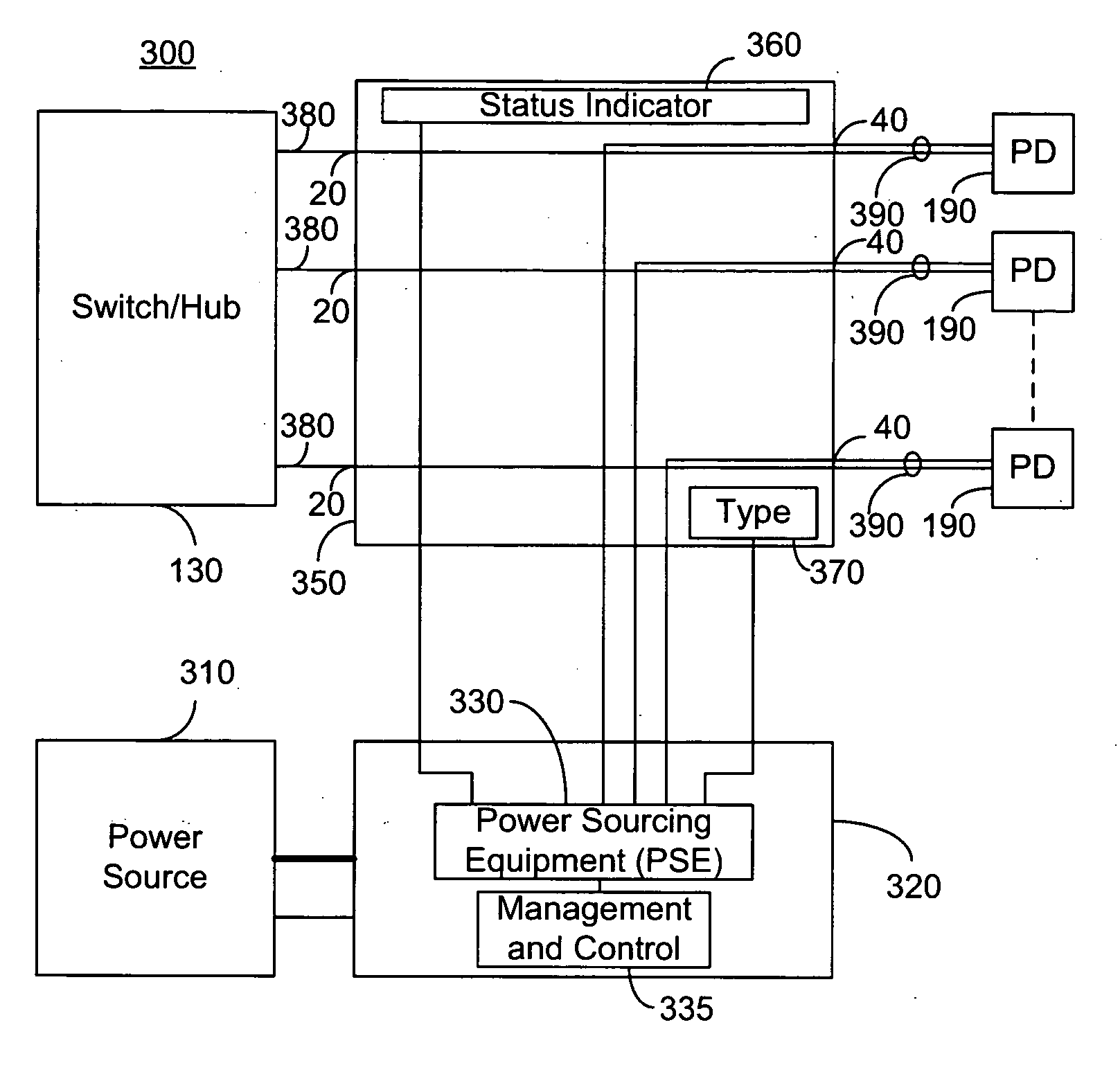
[0053] The present embodiments enable a system for powering nodes over structured cabling by providing a power ready patch panel and a power sourcing device (PSD). The PSD outputs a current limited power for each node to be powered and provides interrogation, optional classification, power management and optional reporting, preferably in conformity with IEEE 802.3af. In an exemplary embodiment, a plurality of PSDs provide power for a plurality of power ready patch panels, and at least one PSD provides rack level power management. The power ready patch panel preferably comprises a connection for receiving power from the power sourcing device, a plurality of ports for connecting switch / hub equipment, a plurality of ports for connecting nodes and a status indicator for each port. Each port for connecting switch / hub equipment is associated with a unique port for connecting a node. Preferably, the power ready patch panel further provides a type indication for each port or group of ports ...


PUM


Abstract

A system for providing power over Ethernet comprising: a plurality of means for receiving a current limited power signal, each of the means receiving a unique current limited power signal; a plurality of means for connecting one end of a cable, the cable comprising a plurality of twisted wire pairs, each of the cables providing a data communication and power path to a particular node connecting jack; a plurality of connectors each for connecting one end of a patch cable, the plurality of connectors being each operatively connected by pairs of conductors to a unique one of the plurality of means for connecting one end of a cable to allow for data communication between the patch cables and the cables; and a plurality of means for injecting the received current limited power signal onto at least one of the pairs of conductors.

Description

CROSS-REFERENCE TO RELATED APPLICATIONS [0001] This application claims priority from U.S. Provisional Patent Application Ser. No. 60 / 625,567 filed Nov. 8, 2004 entitled “System for Providing Power Over Ethernet Through a Patch Panel”; U.S. Provisional Patent Application Ser. No. 60 / 644,002 filed Jan. 18, 2005 entitled “System for Providing Power Over Ethernet Through a Patch Panel”; and is a continuation in part of U.S. patent application Ser. No. 10 / 334,386 filed Dec. 31, 2002 entitled “Integral Board and Module for Power Over LAN”, which is a continuation in part of U.S. patent application Ser. No. 10 / 218,739 filed Aug. 13, 2002 entitled “Structure Cabling System”, which is a continuation of application Ser. No. 09 / 365,584 entitled “Structure Cabling System” filed Aug. 2, 1999 now U.S. Pat. No. 6,473,608, which is a continuation in part of U.S. patent application Ser. No. 09 / 293,343 filed Apr. 16, 1999 entitled “System for Power Delivery Over Data Communication Cabling Infrastruct...

Claims


Application Information

Patent Timeline
Patent Type & Authority Applications(United States)
IPC IPC(8): H04B17/00
CPCH04L12/10G06F1/266
Inventor PINCU, DAVIDKORCHARZ, DROR
Owner CISCO TECH INC
Why Eureka
Try Eureka