Image display apparatus

Active Publication Date: 2006-03-30
JVC KENWOOD CORP A CORP OF JAPAN
View PDF6 Cites 2 Cited by
  • Summary
  • Abstract
  • Description
  • Claims
  • Application Information

AI Technical Summary

Benefits of technology

[0007] Therefore, the present invention is proposed in view of the above-described problem, and it is an object of the present invention to provide an

Problems solved by technology

In this type of image display apparatus, when dust and the like in air are accumulated on a surface of the reflective light bulb, optical performance of the reflective light bulb deteriora

Method used


Image

  • Image display apparatus
  • Image display apparatus
  • Image display apparatus

Examples


first embodiment

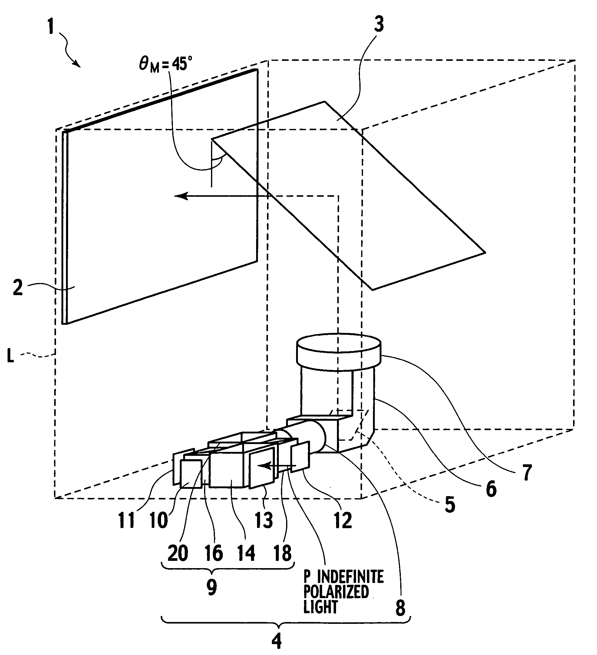
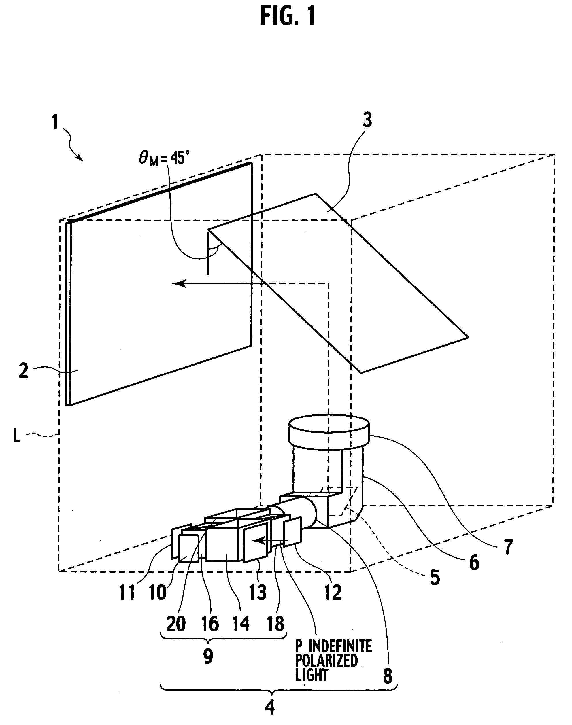
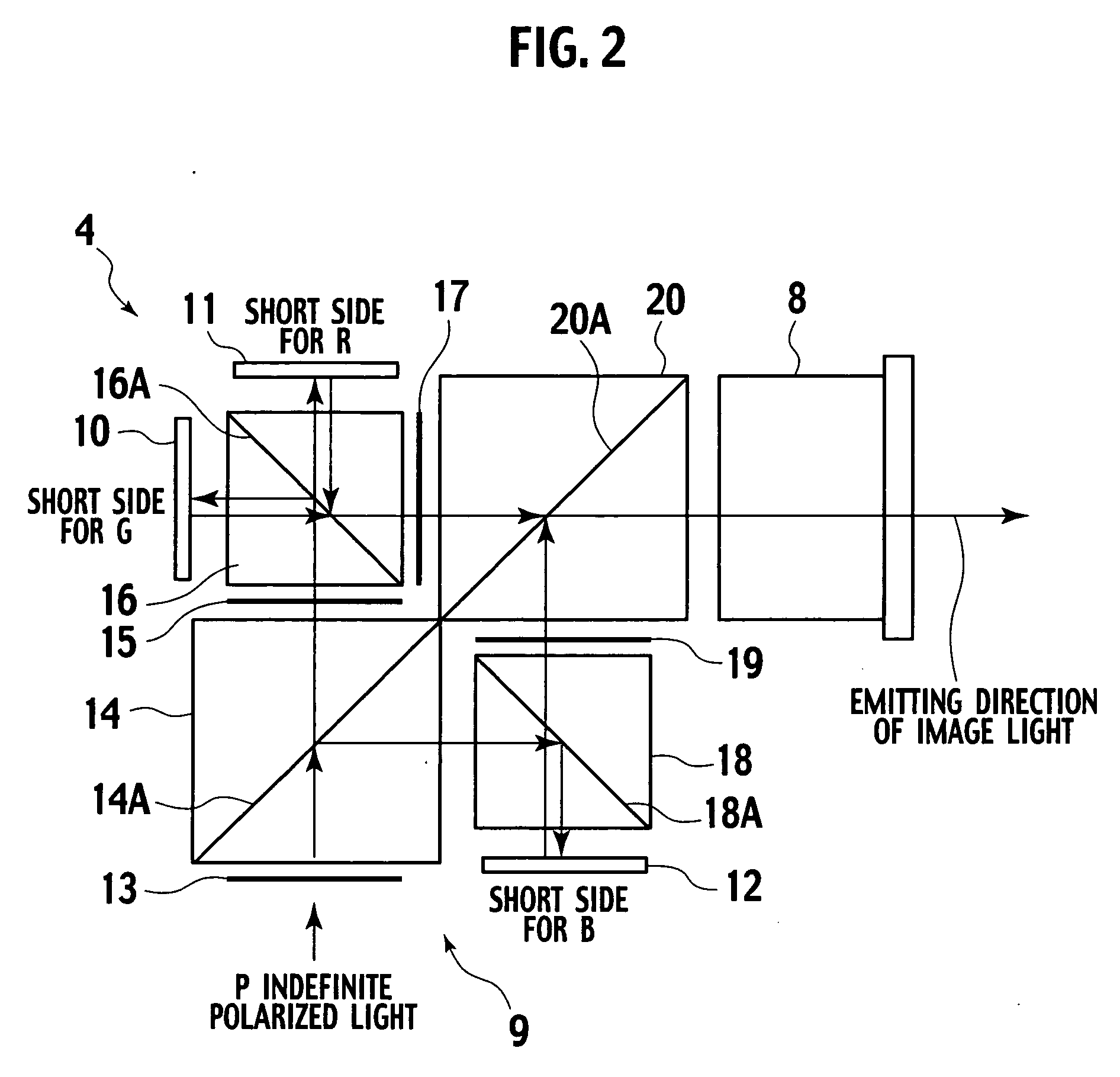
[0022]FIG. 1 is a perspective view showing a first embodiment of an image display apparatus according to the present invention. FIG. 2 is a view illustrating a configuration of a liquid crystal projector. FIG. 3 is a view illustrating an arrangement of a reflecting mirror according to the first embodiment.

[0023] In FIG. 1, constituent components accommodated in a box member L are indicated by solid lines, and a box member L is indicated by broken lines for the convenience's sake.

[0024] As shown in FIG. 1, an image display apparatus 1 according to the first embodiment of the present invention comprises: a plane mirror 3 arranged at an angle θM=45° with respect to a screen 2; a liquid crystal projector 4 arranged between the screen 2 and the plane mirror 3; a reflecting mirror 5 which reflects image light emitted from the liquid crystal projector 4; a light guiding tube 6 in which the reflecting mirror 5 is accommodated; and a projection lens 7 which projects the image light reflect...

second embodiment

[0053] A second embodiment according to the present invention will now be described with reference to FIGS. 4 and 5.

[0054]FIG. 4 is a perspective view showing a second embodiment of the image display apparatus according to the present invention. FIG. 5 is a view illustrating an arrangement of a reflecting mirror according to the second embodiment.

[0055] In FIG. 4, constituent components accommodated in a box member L are indicated by solid lines, and the box member L is indicated by broken lines for the convenience's sake.

[0056] Like reference numerals denote structures equal to those in the first embodiment, thereby eliminating their explanation.

[0057] As shown in FIG. 4, an image display apparatus 24 according to the second embodiment of the present invention has a plane mirror 3 arranged at an angle θM2 in the image display apparatus 1 in the first embodiment. Moreover, as shown in FIG. 5, an incident light axis 21 of image light which falls on a reflecting mirror 5 is within...

third embodiment

[0061] A third embodiment according to the present invention will now be described with reference to FIG. 6.

[0062]FIG. 6 is a perspective view showing a third embodiment of the image display apparatus according to the present invention.

[0063] In FIG. 6, constituent components accommodated in a box member L are indicated by solid lines, and the box member L is indicated by broken lines for the convenience's sake.

[0064] As shown in FIG. 6, an image display apparatus25 according to the third embodiment of the present invention has a plane mirror 26 arranged between the projection lens 7 and the plane mirror 3 in the image display apparatus 24 according to the second embodiment, and any other configuration is the same as the foregoing embodiment.

[0065] According to the third embodiment of the present invention, since the plane mirror 26 is required, the number of components is increased. However, since image light projected from the projection lens 7 is once reflected by the plane m...


PUM


Abstract

The present invention includes a reflection portion which light-modulates three primary color lights by three rectangular reflective liquid crystal light bulbs, then color-combine the light-modulated lights and reflects the resultant light; and a projection lens which projects the reflected color-combined light onto a plane mirror. The three reflective light bulbs are arranged in such a manner that their long side directions coincide with a perpendicular direction, and two of the three reflective light bulbs are arranged in such a manner that their short side directions become parallel with a projecting direction of image light from a color separation/combination optical system.

Description

BACKGROUND OF THE INVENTION [0001] 1. Field of the Invention [0002] The present invention relates to an image display apparatus in which dust and the like are hardly accumulated on a light bulb and which can be reduced in size. [0003] 2. Description of the Related Art [0004] Heretofore, a liquid crystal projector utilizing a light bulb has been present. As an image display apparatus using this liquid crystal projector, there has been known a system which projects a projection image from the liquid crystal projector onto a screen by a projection lens through a plurality of deflecting mirrors. [0005] For example, Japanese Patent Application Laid-open No. 2000-75409 discloses an image display apparatus in which a box member accommodates a reflective light bulb; a color separation / combination optical system which color-separates light emitted from a light source into three primary color lights, then modulates and color-combines these lights by the reflective light bulb to emit image lig...

Claims


Application Information

Patent Timeline
IPC IPC(8): G03B21/26
CPCH04N9/3197H04N9/3141
Inventor YOSHIKAWA, YUAIZAKI, TAKATSUGUSUZUKI, TETSUJIWATANABE, HIROSHI
Owner JVC KENWOOD CORP A CORP OF JAPAN
Why Eureka
Try Eureka