Solar spotlight

a solar and spotlight technology, applied in the field of outdoor solar landscape lighting, can solve the problems of limiting the application of a particular light to limited areas of a landscape, solar collectors cannot be adequately adjusted and/or positioned, and many limitations, so as to increase the flexibility of placement and positioning, and facilitate connection. , the effect of increasing the flexibility of the placement of the ligh

Inactive Publication Date: 2006-08-24
WORLD FACTORY
View PDF9 Cites 68 Cited by
  • Summary
  • Abstract
  • Description
  • Claims
  • Application Information

AI Technical Summary

Benefits of technology

[0009] This object is achieved by providing a solar light having a main housing, a solar housing having at least one solar collector, and at least one light housing. The solar housing and the light housing are each adjustably attached to the main housing to provide increased flexibility in placement and positioning of the solar collector and the light. A support member on the main housing is adapted for quick and easy connection to a stake, a riser, and / or a surface mount, to provide further increased flexibility in placement of the light.
[0010] The present invention provides significant benefits and advantages, including: (1) the solar collector can be adjusted independent of the light housing so as to optimize solar energy collection; (2) the position and orientation of lighting elements can be independently adjusted, thereby allowing more areas to be illuminated by a single light unit; (3) the light can be configured in a low-profile design, thereby reducing the obtrusiveness of the light; and (4) the light housing is adapted to be connected to stakes, risers, surface mounts, and other mounting means.

Problems solved by technology

Solar landscape lights are well known in the art, but have several limitations.
Many of these limitations result in aesthetic problems, while others limit the application of a particular light to limited areas of a landscape.
For example, often the solar collector cannot be adequately adjusted and / or positioned to optimize the collection of solar energy.
In addition, the lighting elements have little or no adjustment capabilities.

Method used


Image

  • Solar spotlight
  • Solar spotlight
  • Solar spotlight

Examples


Embodiment Construction

[0024] The present invention represents the discovery that a highly flexible solar spotlight can solve many lighting problems with a single light unit.

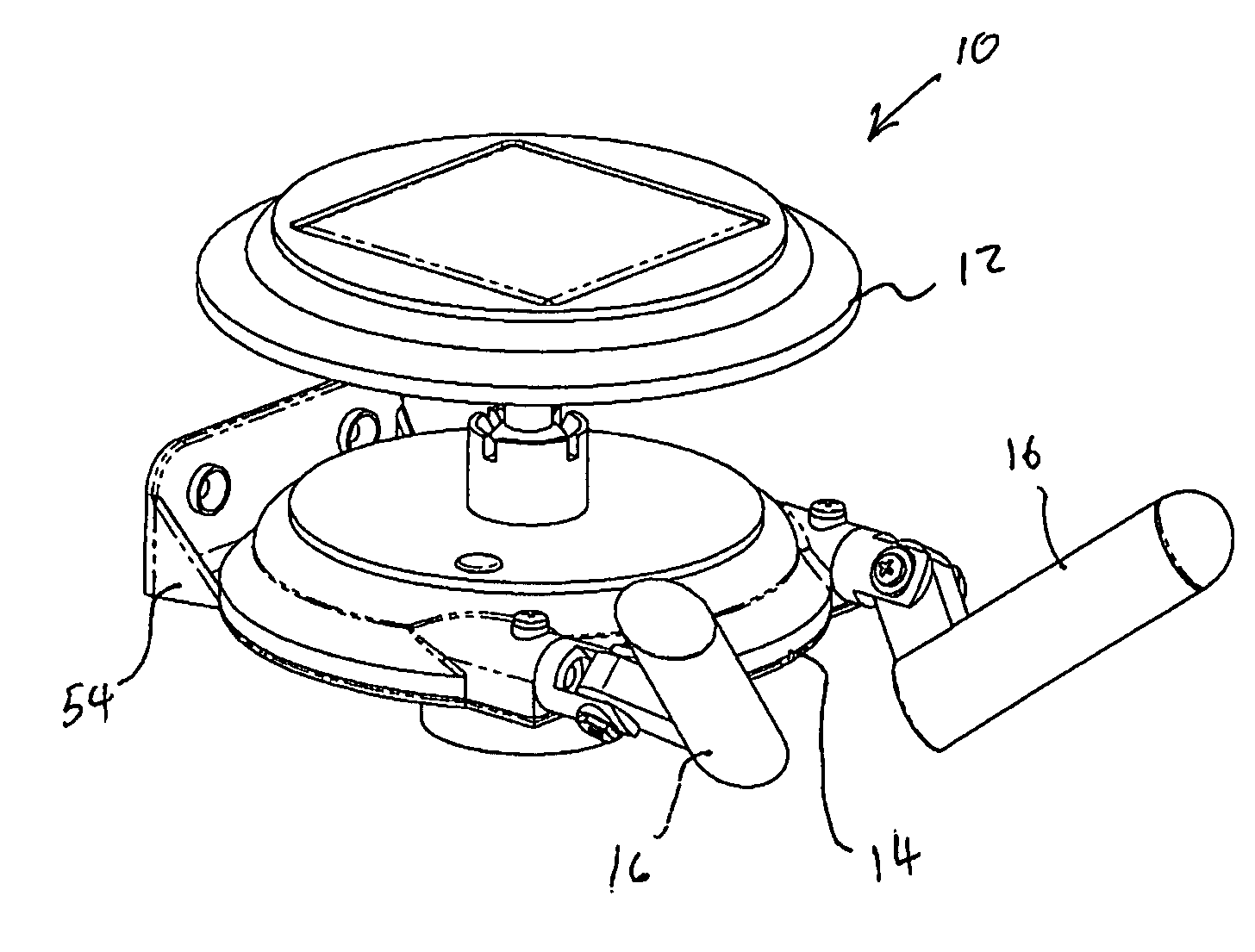
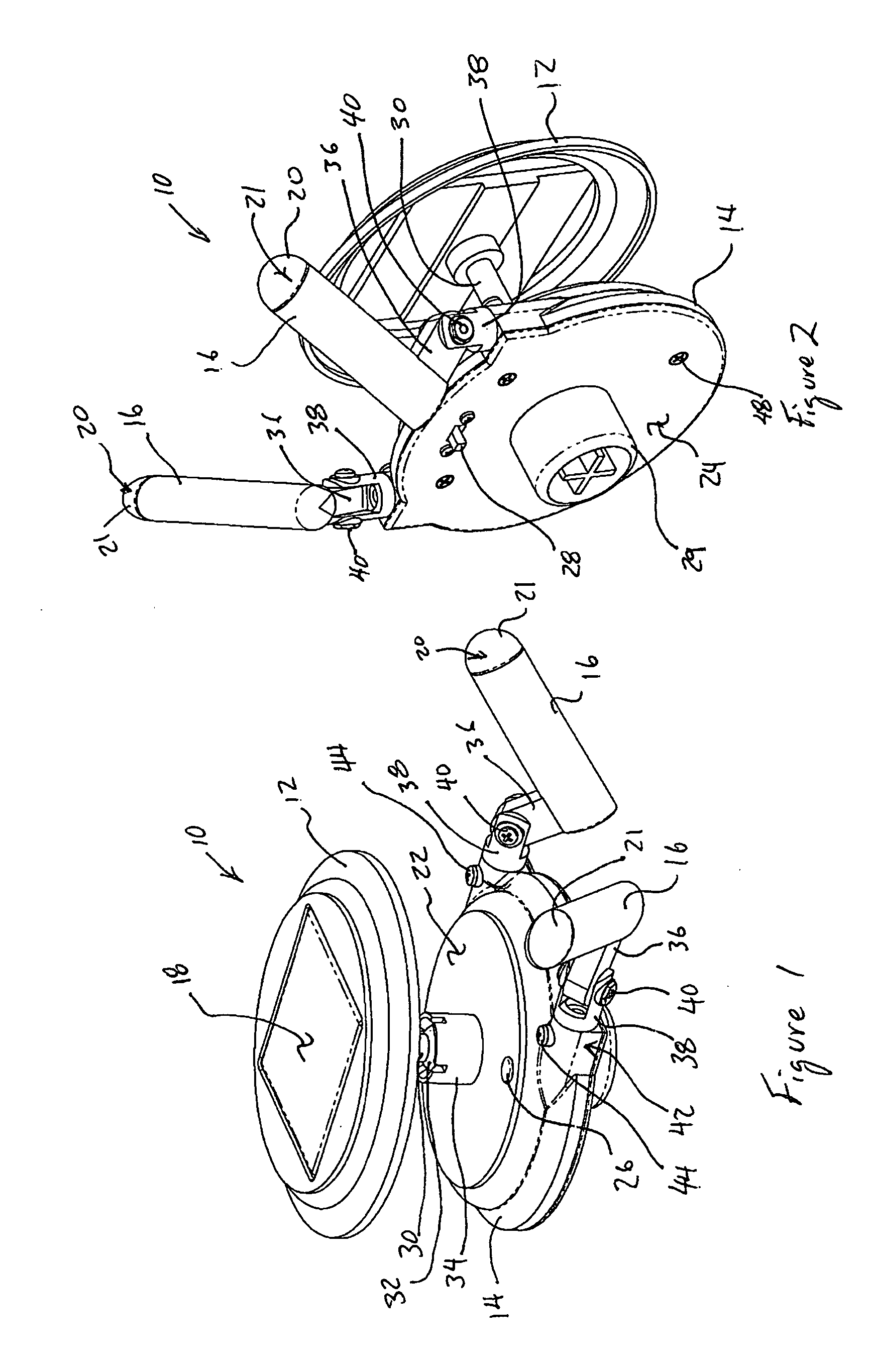
[0025] Referring to FIGS. 1 and 2 of the drawings, a solar spotlight 10 has a solar housing 12, main housing 14, and light housings 16. Light housings 16 and solar housing 12 are coupled to main housing 14. Solar housing 12 carries a solar panel 18 that is photo voltaic, as is described in more detail below. Light housings 16 each carry at least one light element 20 that emits light upon the application of electrical energy, as described in more detail below. Light elements 20 are preferably light emitting diodes (LED's), but may be organic light emitting diodes, incandescent bulbs, cold cathode ray tubes, fluorescent lights, or any other suitable electrical lighting apparatus, or combination thereof. Main housing 14 has an upper surface 22 and a lower surface 24.

[0026] Main housing 14 preferably carries a photo resistor, or photo c...


PUM


Abstract

A solar light has a main housing, a solar housing, and a light housing. The solar housing and the light housing are each coupled to and independently adjustable relative to the main housing to provide increased flexibility in placement, orientation, and configuration of the light. A support member on the main housing is designed for connection to stakes, risers, surface mounts, and other mounting means, to provide further increased flexibility in use of the light.

Description

[0001] This application claims the benefit of U.S. Provisional Application No. 60 / 655,988, filed 24 Feb. 2005, titled “Solar Spotlight.”BACKGROUND OF THE INVENTION [0002] 1. Field of the Invention [0003] The present invention relates to outdoor lighting, and more particularly, to outdoor solar landscape lighting. [0004] 2. Description of Related Art [0005] Solar landscape lights are well known in the art, but have several limitations. Many of these limitations result in aesthetic problems, while others limit the application of a particular light to limited areas of a landscape. For example, often the solar collector cannot be adequately adjusted and / or positioned to optimize the collection of solar energy. In addition, the lighting elements have little or no adjustment capabilities. [0006] Although great strides have been made in the are of solar lighting, many shortcomings remain. SUMMARY OF THE INVENTION [0007] There is a need for a solar light in which the solar collector and at ...

Claims


Application Information

Patent Timeline
Patent Type & Authority Applications(United States)
IPC IPC(8): F21L4/00F21L13/00
CPCF21S9/035F21V21/0824F21V21/22F21V21/30F21V23/0442F21W2131/109F21Y2101/02F21V33/006F21S8/033F21W2131/00F21W2131/10F21S8/081F21Y2115/10Y02B20/72
Inventor KUELBS, GUSTAV P.PU, MINGQIANG
Owner WORLD FACTORY
Why Eureka
Try Eureka