Image forming apparatus having fixing device for fixing toner image on a recording material

a technology of image forming apparatus and recording material, which is applied in the direction of electrographic process, instruments, transportation and packaging, etc., can solve the problems of deformation of recording material, affecting the separation performance, and hurling the surface of heating member, so as to improve separation performance and provide recording material conveyance performance

Inactive Publication Date: 2007-06-28
KONICA MINOLTA BUSINESS TECH INC
View PDF1 Cites 35 Cited by
  • Summary
  • Abstract
  • Description
  • Claims
  • Application Information

AI Technical Summary

Benefits of technology

[0010]An object of the present invention is to solve the problem of the claw separation by using an air separation unit. Further another object of the present invention is to provide an image forming apparatus capable of maintaining good separation performance and to provide recording material conveyance performance by solving the problem of the conventional air separation unit even though the structure of the fixing device is different and the operation mode of the image forming apparatus varies.

Problems solved by technology

However there are problems that the separation claw hurts the surface of the heating member and deforms the recording material.
Further the separation claw itself is deformed and results in deterioration of separation performance.
However, a conventional air separator is not enough as a separator in the following points.
With regard to the width direction perpendicular to the conveyance direction of the recording material, when air emitting amount distribution is not appropriate, there is a problem that separation failure and flapping of the recording material occur.
However, since the air emitting amount distribution becomes high in an end portion according to the structure, there is a problem that separation failure tends to occur.

Method used


Image

  • Image forming apparatus having fixing device for fixing toner image on a recording material
  • Image forming apparatus having fixing device for fixing toner image on a recording material
  • Image forming apparatus having fixing device for fixing toner image on a recording material

Examples


embodiment 1

(1) Embodiment 1

[0052]FIG. 6 illustrates the main portion of the embodiment 1 of the present invention.

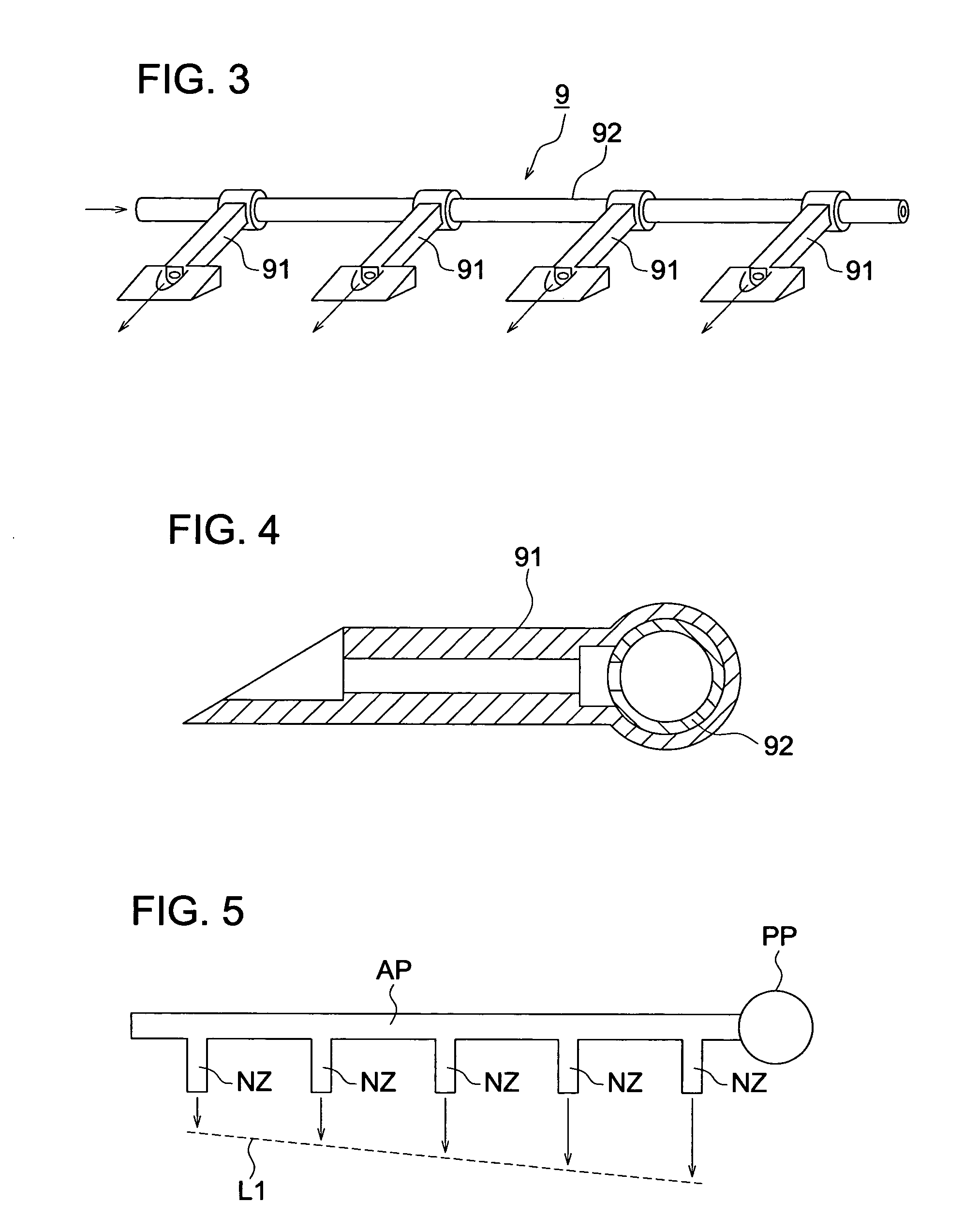
[0053]A plurality of nozzles 91, which are arrayed in the width direction, namely the X direction, which is orthogonal to the conveyance direction Y. The plurality of nozzles 91 are connected to a common guiding pipe 92 and compressed air is sent from an air pump 94a and an electro-magnetic valve 93a to one end of the guiding pipe 92.

[0054]An air pump 94b and an electro magnetic valve 93b are disposed at the other end of the guiding pipe 92. Air(Gas) is supplied from the both ends of the guiding pipe 92. Thus, as illustrated in a dotted line L2, air having a uniform air emitting amount distribution in the width direction X is emitted from the nozzles 91.

[0055]The disposed plurality of nozzles 91, the common guiding pipe 92, the air pumps 94a-94b and the electro magnetic valves 93a-93b constitute the air emitting amount distribution setting section.

[0056]By blowing air against the h...

embodiment 2

(2) Embodiment 2

[0057]FIG. 7 illustrates the main portion of the embodiment 2 of the present invention.

[0058]In this embodiment, an air pump 94 and an electro magnetic valve 93 are connected with a center portion of the guiding pipe 92 in the recording material width direction. The disposed plurality of nozzle 91, the common guiding pipe 92, the air pump 94 and the electro magnetic valve 93 constitute the air emitting amount distribution setting section.

[0059]According to this configuration, as illustrated in a dotted line L3, conducted is air blowing having the air emitting amount having a mountain shape air distribution in which the peak point is set in the center portion in the recording material width direction.

[0060]In this embodiment, when conducting image formation onto a large size recording material such as A3 size recording material and A4 size longitudinal (recording material conveyance with setting a longitudinal side of the recording material to the width direction), th...

embodiment 3

(3) Embodiment 3

[0063]FIG. 9 illustrates the main portion of the embodiment 3 of the present invention.

[0064]In the embodiment, as illustrated in FIG. 9, the air pump 94 and the electro magnetic valve 93 supply air to the guiding pipe 92 at the position being nearer to one end of the guiding pipe 92. The disposed plurality of nozzles 91, the common guiding pipe 92, the air pump 94 and the electro magnetic valve 93 constitute the air emitting amount distribution setting section. According to the structure described above, as illustrated in a dotted line L4, a sail type air emitting amount distribution having the peak of the air emitting amount at the position adjacent to the one end is formed.

[0065]The embodiment can be applied to the image forming apparatus having a sheet conveyor for conveying various size recording materials P1-P4 in the Y direction by referring to a standard line SL as illustrated in FIG. 10.

[0066]The conveyance referring to the one side reference is conducted in...


PUM


Abstract

An image forming apparatus having a fixing device for fixing toner image on a recording material, the fixing device includes: a heating member which heats a recording material; a pressing member which comes into contact with the heating member with pressure; and an air separator which separates the recording material from the heating member by compressed air blown between a leading edge of the recording material and the heating member, the air separator includes a plurality of nozzles disposed in a width direction perpendicular to a conveyance direction of the recording material and an air emitting amount distribution setting section which unifies an emitting amount distribution in the width direction of the compressed air which is emitted from the nozzles.

Description

[0001]This application is based on Japanese Patent Application No. 2005-377178 filed on Dec. 28, 2005, which is hereby incorporated by reference.BACKGROUND OF THE INVENTION[0002]The present invention relates to an image forming apparatus and particularly relates to separation technology of recording material in a fixing device of an image forming apparatus.[0003]An electrophotographic image forming apparatus, in general, includes a fixing device for fixing a toner image onto a recording material by giving heat and pressure to the toner image on the recording material by using a heat member and a pressing member.[0004]In the fixing device of the image forming apparatus, due to the viscosity of the toner, which has been heated and melted, the recording material tends to adhere to the heating member. Thus, in order to separate the recording material from the heating member, a separator for separating the recording material after fixing operation from the heating member is used. With re...

Claims


Application Information

Patent Timeline
Patent Type & Authority Applications(United States)
IPC IPC(8): G03G15/20
CPCY10S271/90G03G15/2028
Inventor FUJII, MAKOTO
Owner KONICA MINOLTA BUSINESS TECH INC
Why Eureka
Try Eureka