Printing Apparatus and Printing Method

a printing apparatus and printing method technology, applied in the direction of digital output to print units, instruments, sensing by electromagnetic radiation, etc., can solve the problems of cumbersome reading of such objects, burdensome operations, and difficult to specify reading objects, so as to facilitate the reading operation and the reading operation. , the effect of easy reading

Inactive Publication Date: 2007-08-16
SEIKO EPSON CORP
View PDF4 Cites 53 Cited by
  • Summary
  • Abstract
  • Description
  • Claims
  • Application Information

AI Technical Summary

Benefits of technology

[0010]According to one aspect of the invention, there is provided a printing apparatus. The printing apparatus comprises: an image creating device which creates a plurality of two-dimensional code images; an interval setting device which sets an interval between the plurality of two-dimensional code images; and a printing device which prints the plurality of two-dimensional code images having the interval set therebetween by the interval setting device.
[0011]According to another aspect of the invention, there is provided a printing method. The printing method comprises: an image creating step of creating a plurality of two-dimensional code images; an interval setting step of setting an interval between the plurality of two-dimensional code images; and a printing step of printing the plurality of two-dimensional code images having the interval set therebetween by the interval setting step.
[0012]According to these configurations, the user can set an interval between a plurality of two-dimensional code images considering readability or the like because he / she is permitted to set the same by himself / herself. By setting the interval to be relatively wide and printing the plurality of two-dimensional code images, for example, it is made easier to make them fall within the reading area of a code reader. As a result, the user can easily perform a reading operation. Furthermore, even with a code reader having a wide reading portion, the user can easily perform a reading operation without changing the reading direction thereof. Note that examples of two-dimensional codes include QR-code, micro QR-code, Maxi code, Veri-code, data matrix, PDF 417, or the like.
[0013]In this case, it is preferable that the interval setting device secure a margin necessary for the two-dimensional code images and include a plurality of alternatives by which the interval is selected and set to make the two-dimensional code images fall within a printing medium.
[0014]According to this configuration, the user can set an interval between a plurality of two-dimensional code images by a simple operation. Furthermore, it is possible to set an interval within a proper range considering a margin necessary for two-dimensional code images and a print medium. Note that the interval between the plurality of two-dimensional code images may be either a width considering an individual margin width of the two-dimensional code images adjacent to each other or a common width corresponding to the two-dimensional code images overlapping each other.
[0015]In these cases, it is preferable that the plurality of two-dimensional code images be formed of a plurality of divided two-dimensional code images resulting from division of a series of input data.

Problems solved by technology

According to the configuration of JP-A-11-007484, on the other hand, there arises a primary problem involving the user's inability to set a desired interval between a plurality of divided two-dimensional code images, which in turn makes the reading thereof cumbersome.
In view of this, the same problem can be caused also when a plurality of single two-dimensional code images are arranged side by side.
As is often the case with a code reader (also used for reading bar codes) having a wide reading portion in particular, it is not easy to specify the reading object when reading in the lengthwise direction thereof for reasons of the shape of the reading portion, with the two-dimensional code images horizontally arranged adjacent to each other.
Therefore, it is required to change the reading direction from the lengthwise direction to the lateral direction, which in turn requires a burdensome operation.
In addition, when a single two-dimensional code image and a plurality of divided two-dimensional code images are printed at even intervals in a state in which they are horizontally arranged side by side, it is not possible for the user to visually distinguish one from another, which in turn makes a reading process burdensome also.
Furthermore, according to the configuration of JP-A-2003-084950, there arises a secondary problem when a single QR-code image and a plurality of divided QR-code images are printed on a label sheet side by side with the position detection patterns thereof held in the standard position, assuming that they are identical in size.
To begin with, it is not possible even to find the mixed coexistence of the single QR-code image and the plurality of divided QR-code images.
Therefore, a reading process becomes burdensome when both a single QR-code image and a plurality of divided QR-code images exist together.

Method used


Image

  • Printing Apparatus and Printing Method
  • Printing Apparatus and Printing Method
  • Printing Apparatus and Printing Method

Examples


second embodiment

[0082]Next, a description will be made about the tape printer 1 with reference to FIGS. 10A to 14B. Note that only different parts will be described herein so as to avoid overlaps. In lieu of the interval setting function described above, the tape printer 1 has a code image rotating function (code image rotating device) composed of a rotation angle setting program for setting rotation angles of created QR-code images and a rotation executing program for rotating the QR-code images based on the rotation angles set by the rotation angle setting program. Also, the RAM of the tape printer 1 has provided therein a rotation angle storing area for storing the rotation angles 83 set by the rotation angle setting program. Hereinafter, a user's operating procedure for controlling the code image rotating function and the rotation angle storing area will be described with reference to FIGS. 10A to 10D and 11A to 11C.

first embodiment

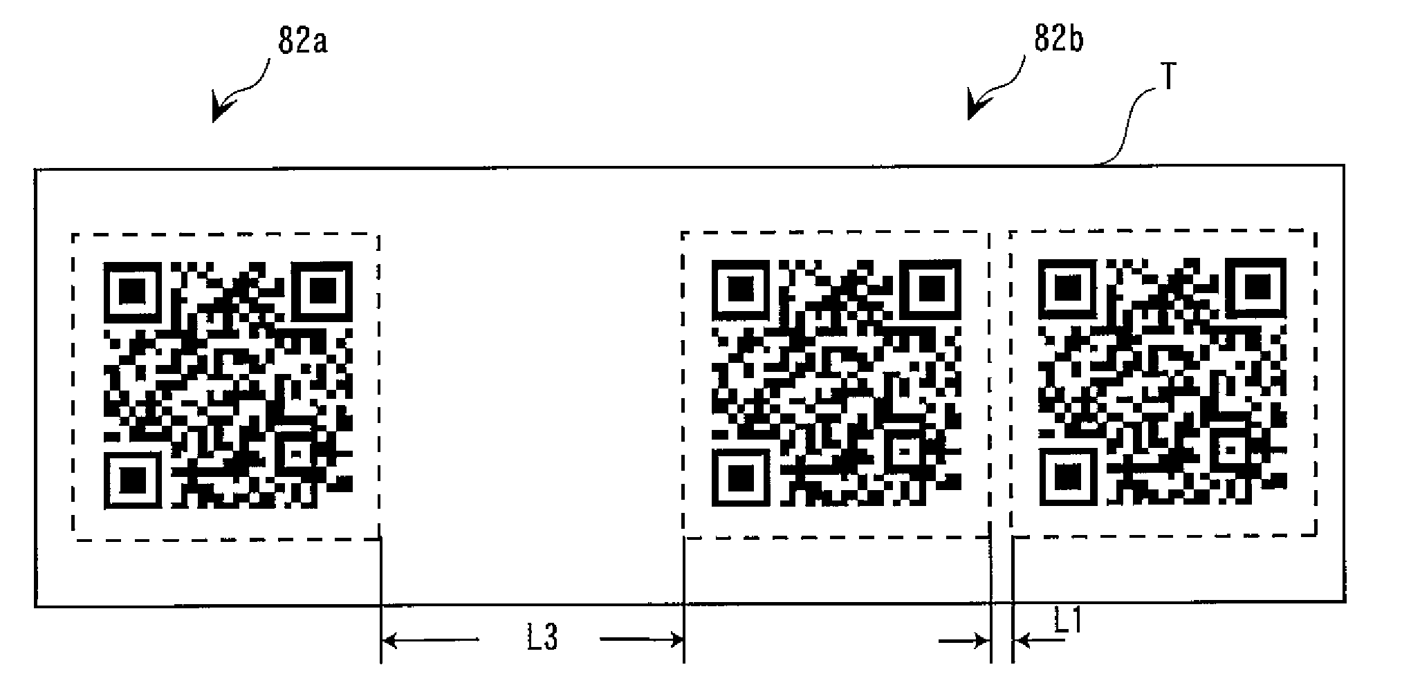
[0083]When any one of the alternatives “TWO-WAY DIVISION,”“THREE-WAY DIVISION,” and “FOUR-WAY DIVISION” is selected in the division setting menu 103 as in the first embodiment, the screen transits to a rotation angle setting menu 104 in which respective rotation angles 83 for the plurality of divided OR-code images 82b are set.

[0084]Selectively displayed in the rotation angle setting menu 104 are alternatives “AUTOMATIC,”“NO ROTATION,”“90°,”“180°,” and “270°.” The rotation angle setting menu 104 is sequentially displayed by the number of divisions selected in the division setting menu 103. In other words, when the alternative “TWO-WAY DIVISION” is selected in the division setting menu 103, a first rotation angle setting menu 104a for rotating one divided QR-code image 82b is displayed (see FIG. 10B). After any one of the alternatives is selected from the rotation angle setting menu 104, a second rotation angle setting menu 104b for rotating the other divided QR-code image 82b is dis...


PUM


Abstract

There is provided a printing apparatus including: an image creating device which creates a plurality of two-dimensional code images; an interval setting device which sets an interval between the plurality of two-dimensional code images; and a printing device which prints the plurality of two-dimensional code images having the interval set therebetween by the interval setting device.

Description

[0001]The entire disclosure of Japanese Patent Application Nos. 2006-038602 filed Feb. 15, 2006 and 2006-041131 filed Feb. 17, 2006 is expressly incorporated by reference herein.BACKGROUND[0002]1. Technical Field[0003]The present invention relates to a printing apparatus and a printing method for creating two-dimensional code images based on input data and printing the same on a print object.[0004]2. Related Art[0005]A known printing apparatus as used hitherto is of a type which has a function of dividing input data for a two-dimensional code image (QR-code image) into plural units to create a plurality of divided two-dimensional code images and that of printing the same. Reference is made to JP-A-11-007484 as an example of related art. For example, when the amount of input data exceeds the maximum data amount which can be stored in a single two-dimensional code, the printing apparatus having such a dividing function divides the input data into plural units to create a plurality of ...

Claims


Application Information

Patent Timeline
Patent Type & Authority Applications(United States)
IPC IPC(8): G06K7/10G06F15/12
CPCG06K19/06037
Inventor TAKAYAMA, SHOJI
Owner SEIKO EPSON CORP
Why Eureka
Try Eureka