

Electrical connector with improved fastener
a technology of electric connectors and fasteners, applied in the direction of electrical apparatus, connection, coupling device connections, etc., can solve the problems of avulsed rivet portion, difficult manufacture, insufficient appearance of electrical connectors, etc., and achieve the effect of convenient assembly
- Summary
- Abstract
- Description
- Claims
- Application Information
AI Technical Summary
Benefits of technology
Problems solved by technology
Method used
Image

Examples
Embodiment Construction
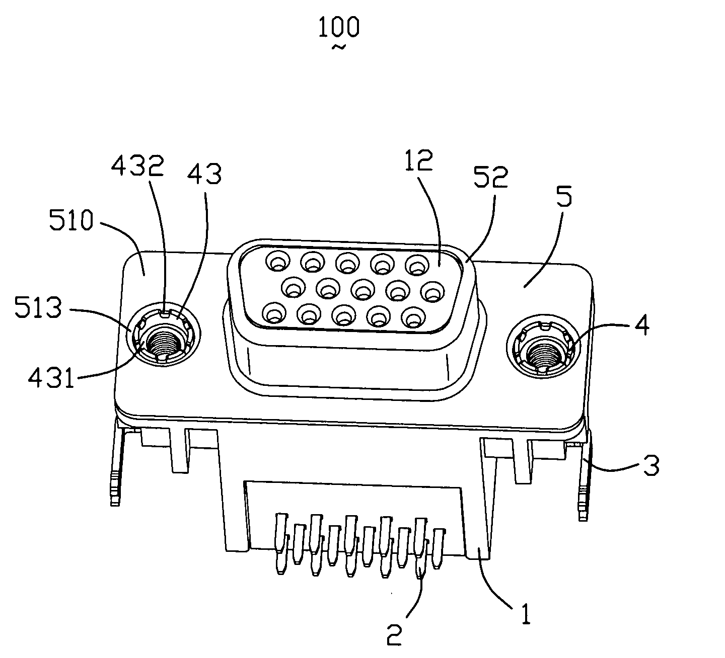
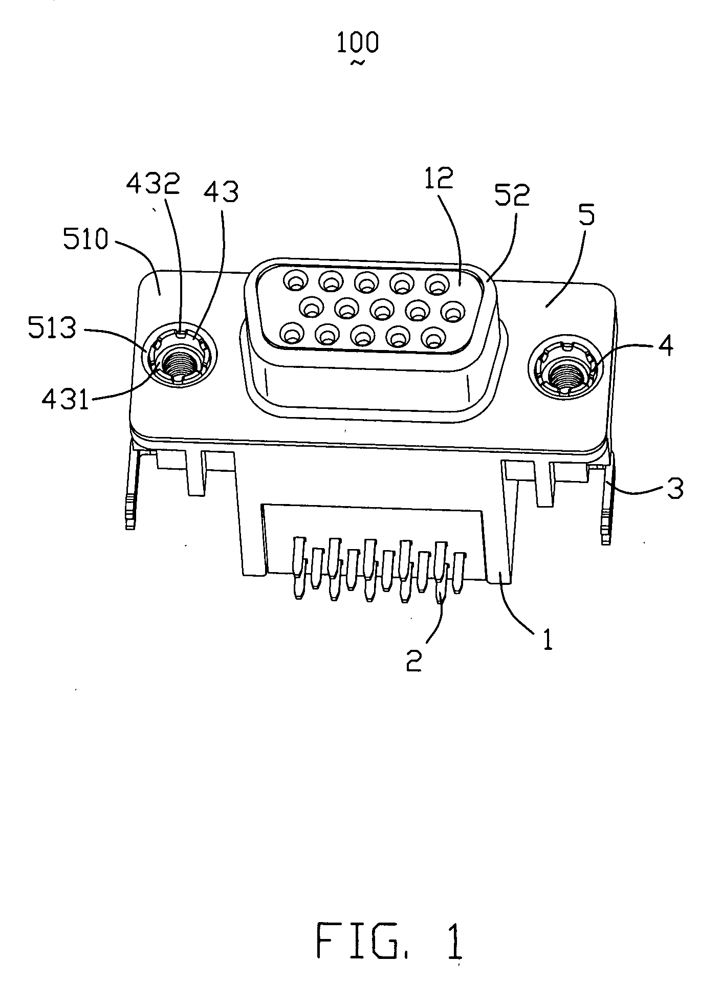
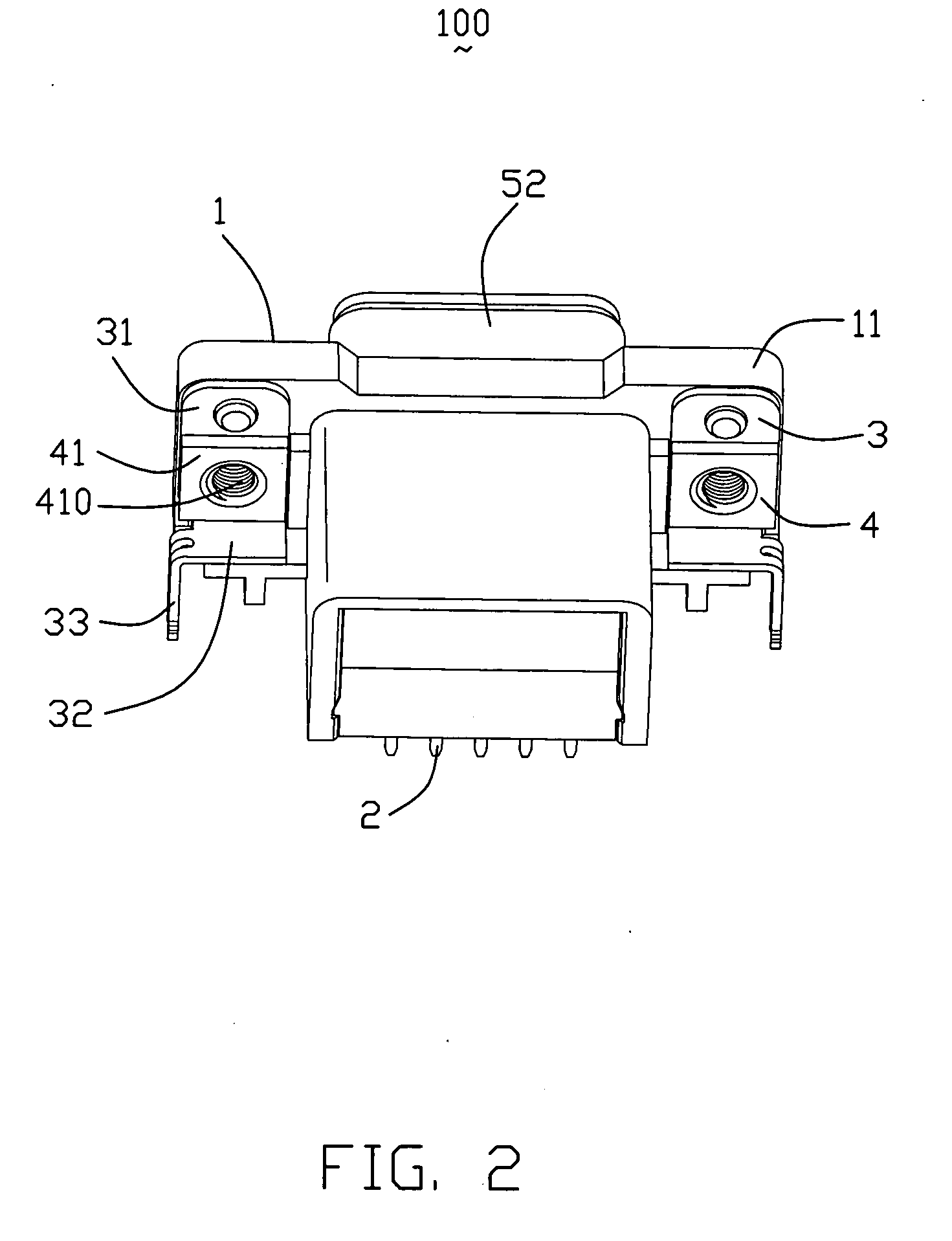
[0014]Referring to FIGS. 1-4, an electrical connector 100 includes an insulative housing 1, a plurality of contacts 2 retained in the insulative housing 1, a metal shell 5 enclosing the insulative housing 1, a pair of board locks 3 and a pair of fasteners 4 for assembling the board locks 3 and the metal shell 5 onto the insulative housing 1.
[0015]Referring to FIG. 3, the insulative housing 1 comprises a base portion 11 and a protrusion 12 extending from a front surface 110 of the base portion 11. The base portion 11 defines a pair of apertures 112 extending through the front surface 110 and a rear surface 111 thereof wherein the apertures 112 are positioned on lateral sides of the base portion 11.
[0016]The metal shell 5 comprises a flat mating portion 51 to be attached to the front surface 110 of the insulative housing 1 and a hollow D-shaped projection 52 protruding forwardly from the mating portion 51 for receiving the corresponding protrusion 12 of the insulative housing 1. The m...
PUM
 Abstract
Description
Claims
Application Information