Liner hanger

a liner and slip technology, applied in the direction of fluid removal, sealing/packing, borehole/well accessories, etc., can solve the problems of high manufacturing cost, frequent rotation of the circumference piston, limited maximum working pressure, etc., to improve the initial bite of the slip, increase the number of springs, and facilitate assembly and disassembly

Active Publication Date: 2008-06-12
BAKER HUGHES INC
View PDF9 Cites 37 Cited by
  • Summary
  • Abstract
  • Description
  • Claims
  • Application Information

AI Technical Summary

Benefits of technology

[0025]The liner hangers disclosed herein have one or more the advantages of: providing an easy to assemble and disassemble liner hanger; providing a vent port for venting and oiling the piston such that the piston can be solid i...

Problems solved by technology

These designs presented a pressure rating problem in that the full circumference piston frequently had a maximum working pressure significantly lower than the mandrel which it surrounded.
Thus, this type of design limited the maximum working pressure in the string to the rating of the cylindrical piston housing assembly.
This design, however, was expensive to manufacture, had many potential leak paths in the form of the ring seals on each of the pistons wherein each slip required two pistons.
The design in U.S. Pat. No. 5,417,288 also did not provide for flexibility for changed conditions downhole which could require additional force to set the slips.
The foregoing prior designs, particularly those using a cylindrical piston...

Method used


Image

  • Liner hanger
  • Liner hanger
  • Liner hanger

Examples


Embodiment Construction

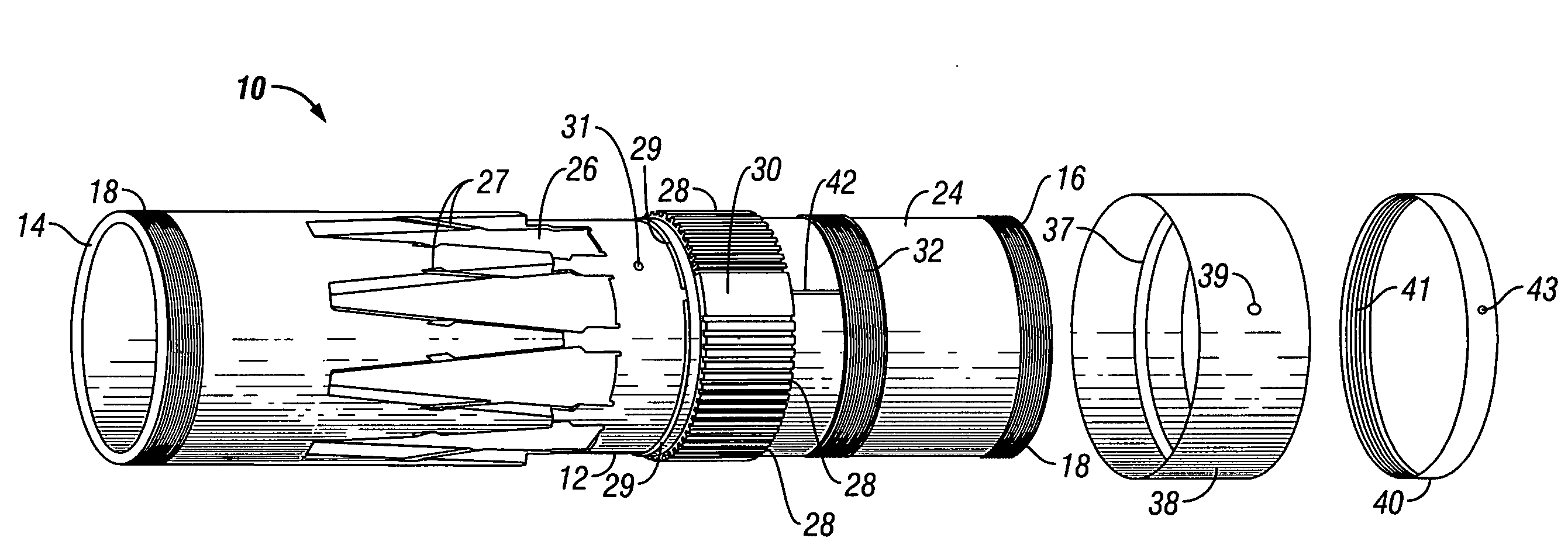
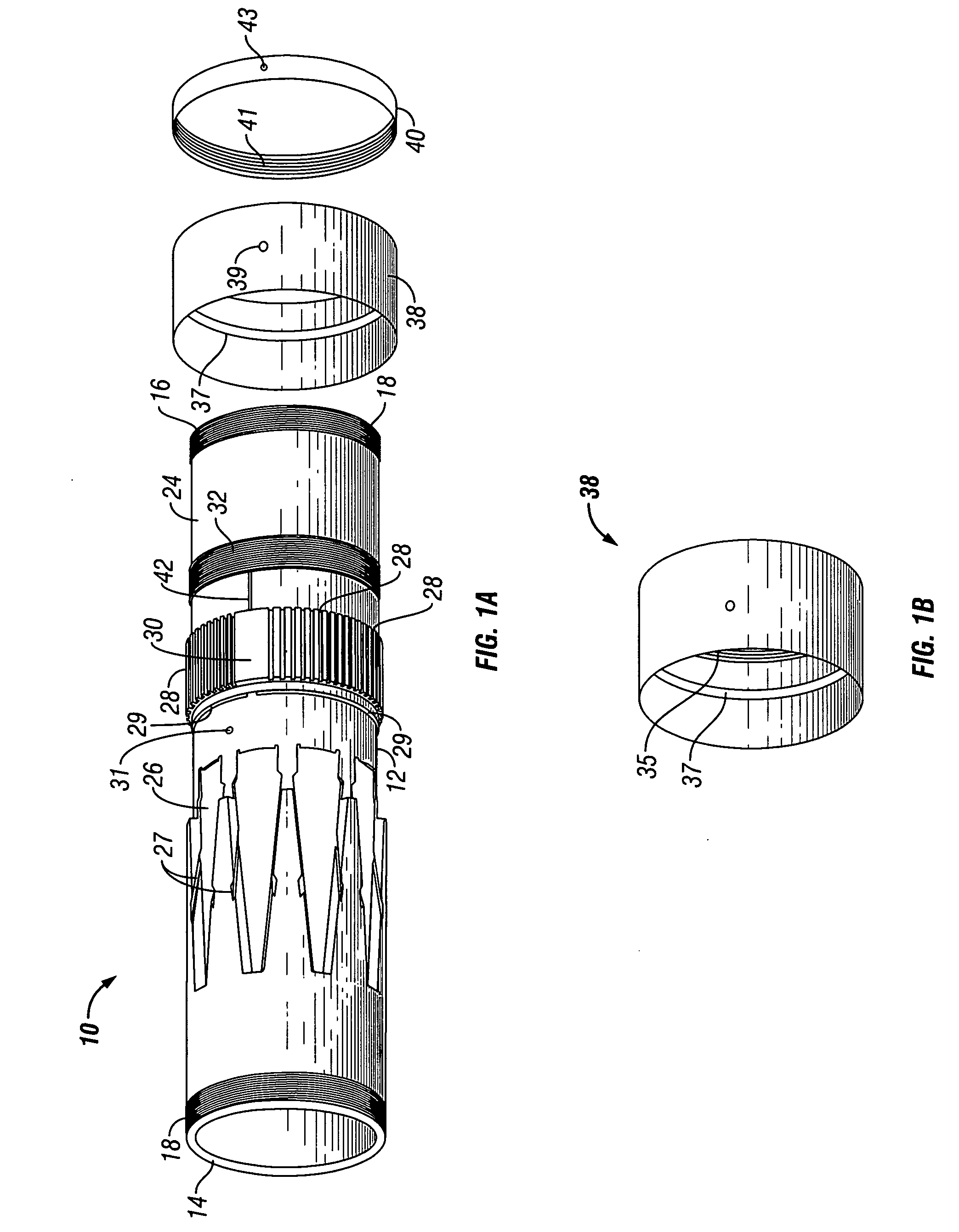
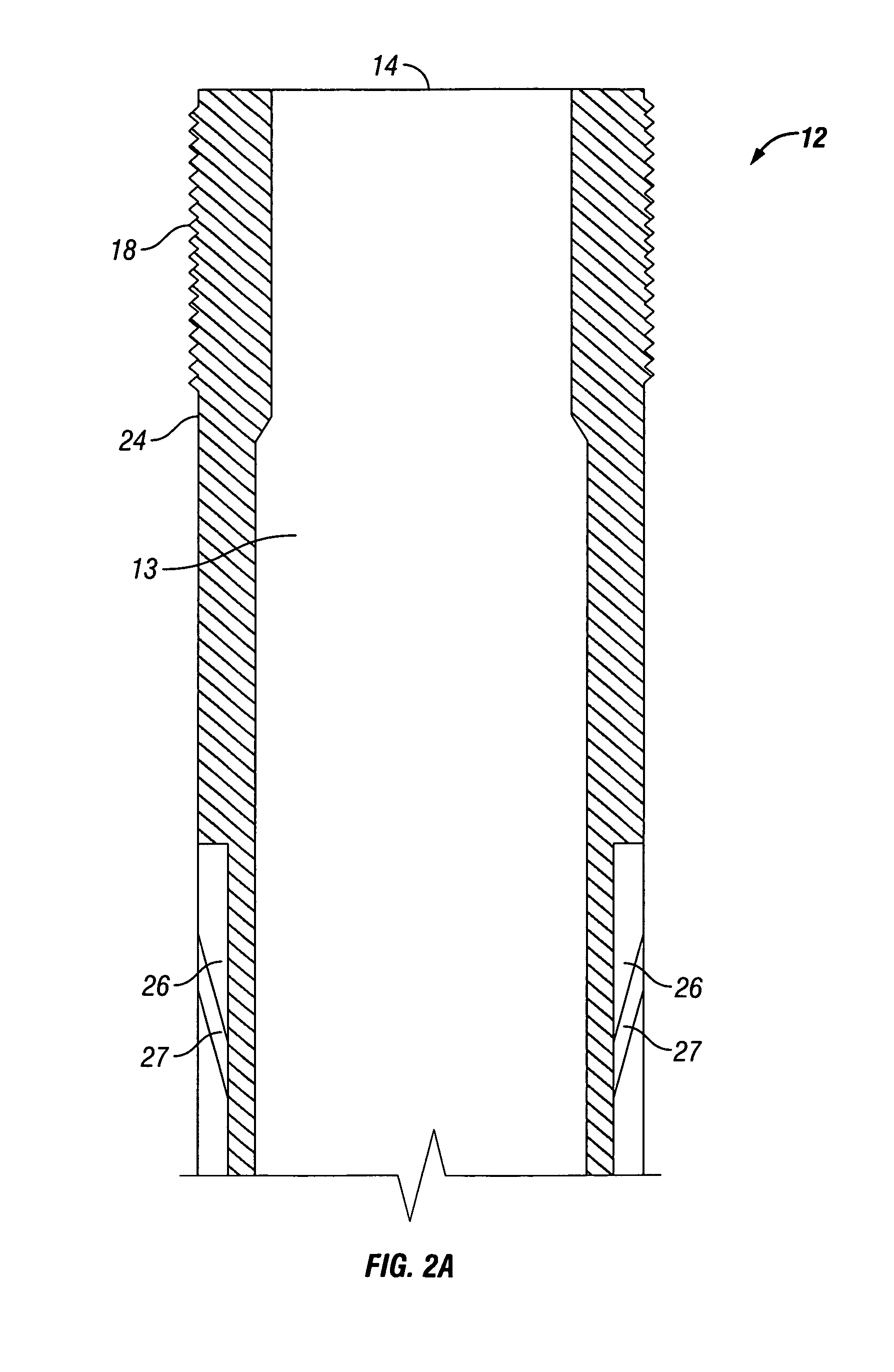
[0046]Referring now to FIGS. 1-13, in one specific embodiment, liner hanger 10 comprises body or mandrel 12 having bore 13, upper end 14, and a lower end 16. Both upper end 14 and lower end 16 are in fluid communication with bore 13 and are adapted to receive additional components of string (not shown). For example, lower end 16 includes threads 18 for matingly engaging another component such as a packer (not shown). As shown in FIG. 2A, upper end 14 also includes threads 18 for attachment to a blow-out preventer, diverter, Christmas tree, riser, tubing, casing, or other piece of equipment.

[0047]The outer wall surface 24 of mandrel 12 includes a plurality of slip pockets 26, a plurality of spring slots 28, piston housing 30, and ring threads 32. As shown in FIGS. 1A, 2B, 3A, 3D, 5 and 6, piston housing 30 is disposed between spring slots 28. Each slip pocket 26 is designed to receive a slip 70; each spring slot 28 is designed to receive a spring 36; and ring threads 32 are for secur...


PUM


Abstract

An improved liner hanger comprises a mandrel having a piston housing and a plurality of spring slots disposed on the outer wall surface of the mandrel. Each spring slot having at least one spring disposed therein. The liner hanger also has a slip housing having a plurality of slips operatively associated therewith, a spring adjustment sleeve, and an adjustment sleeve ring. The location of the spring slots on the outer wall surface of the mandrel permits an increase in the number of springs utilized for setting the liner hanger. The spring adjustment sleeve and adjustment sleeve ring permit easy and safe assembly and disassembly of the liner hanger. Additionally, when actuated to move from its run-in position to its set position, springs, slip housing, and slips all move upward.

Description

BACKGROUND[0001]1. Field of Invention[0002]The invention is directed to anchoring slip assemblies and, in particular, liner hanger devices used for suspending a liner within a wellbore.[0003]2. Description of Art[0004]A liner is a tubular member that is usually run inside of wellbore casing of an oil or gas well and suspended within the wellbore casing. Liners are typically secured within a wellbore by toothed slips that are located on liner hangers. The slips are set by axially translating them with respect to the liner hanger mandrel or housing. As the slips are translated axially, they are cammed radially outwardly by a ramped surface that is fashioned into the mandrel. As the slips move radially outwardly, the toothed surfaces of the slip will bitingly engage the inner wall surface of the wellbore casing. This type of arrangement is shown, for example, in U.S. Pat. No. 4,497,368 in which slips that are radially expanded by riding up over cone elements disposed into the tubular b...

Claims


Application Information

Patent Timeline
IPC IPC(8): E21B23/01
CPCE21B33/0422E21B43/10
Inventor MCGILVRAY, MARK A.FRASER, JAMES M.
Owner BAKER HUGHES INC
Why Eureka
Try Eureka