

Compact flashlight
- Summary
- Abstract
- Description
- Claims
- Application Information
AI Technical Summary
Benefits of technology
Problems solved by technology
Method used
Image

Examples
Embodiment Construction
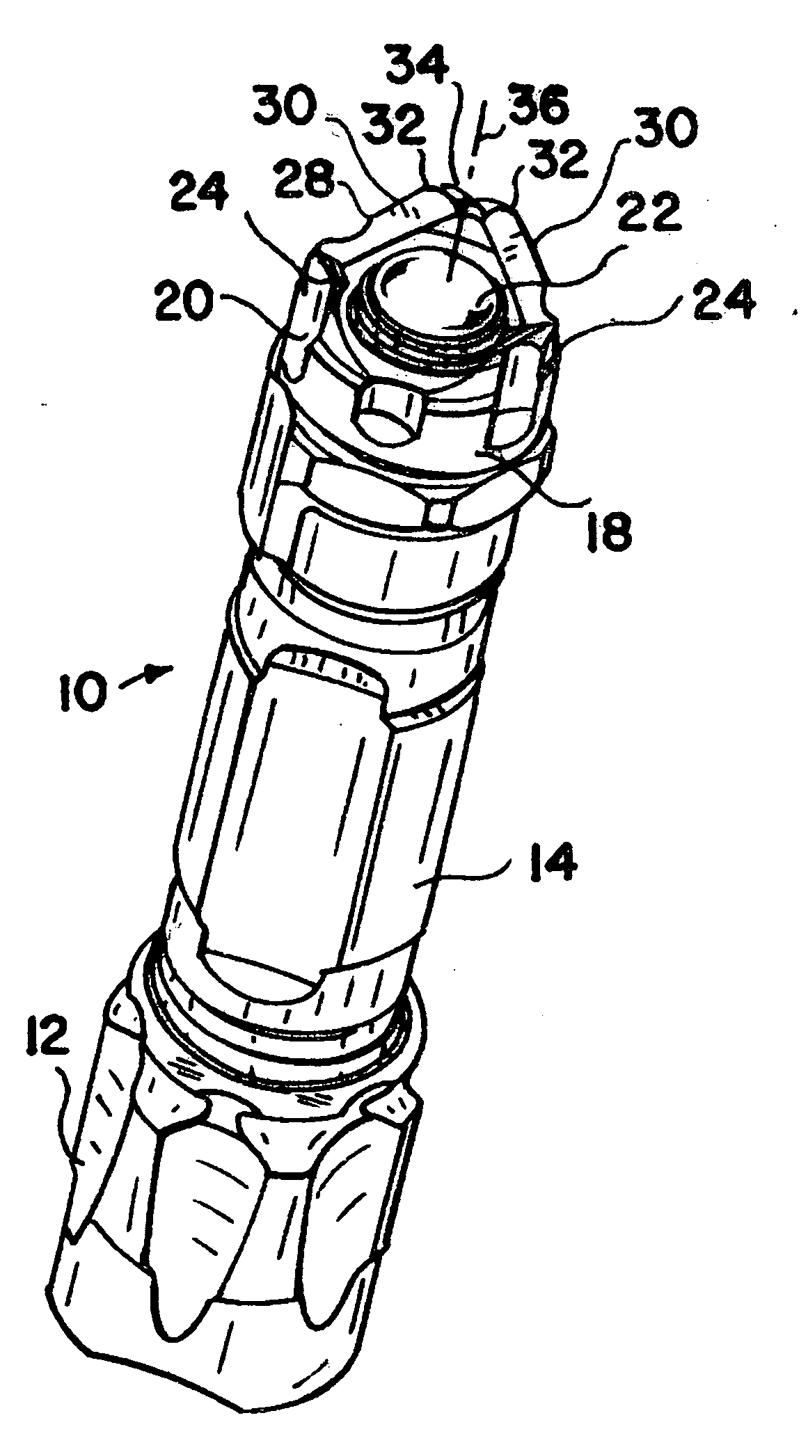
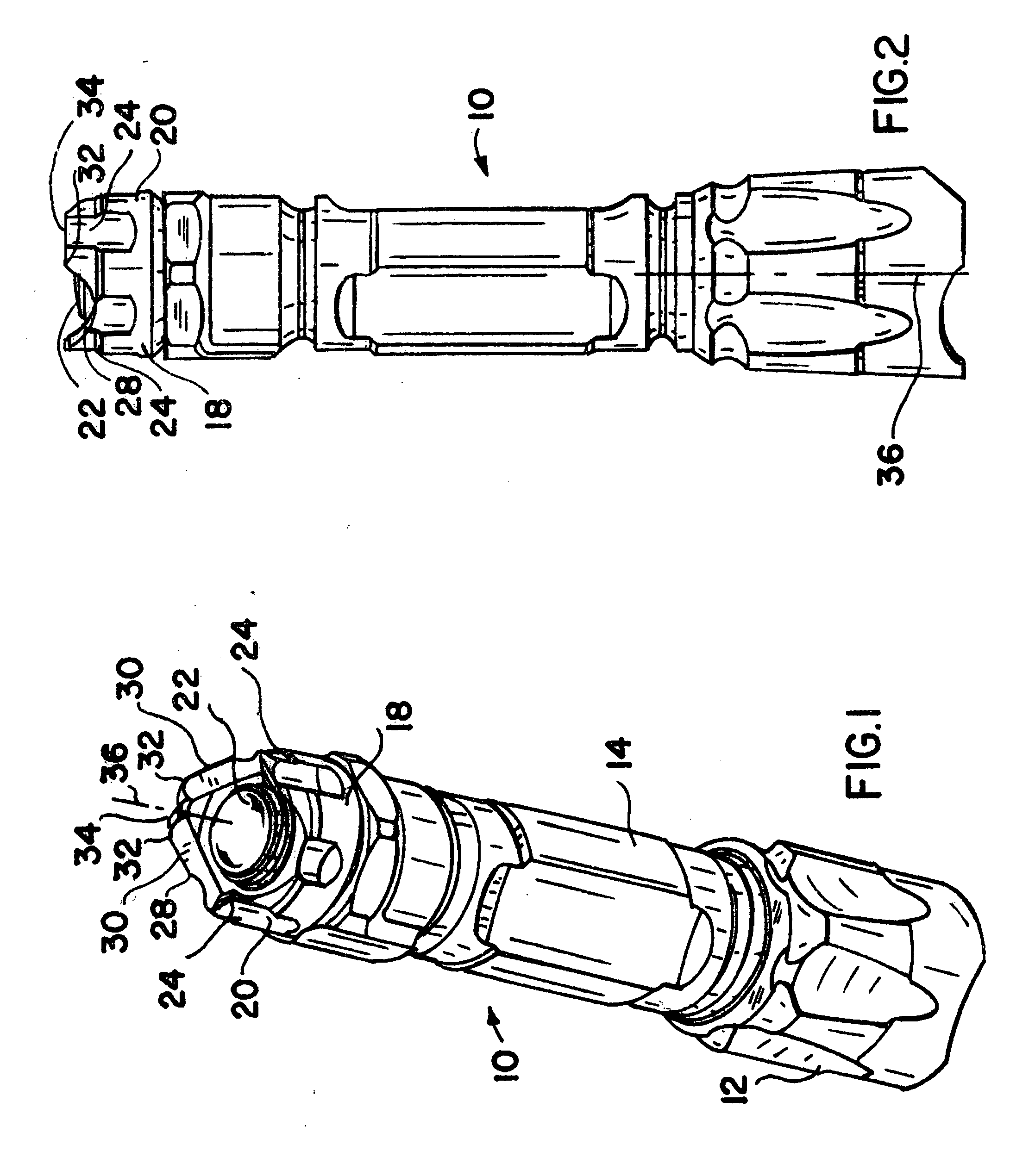
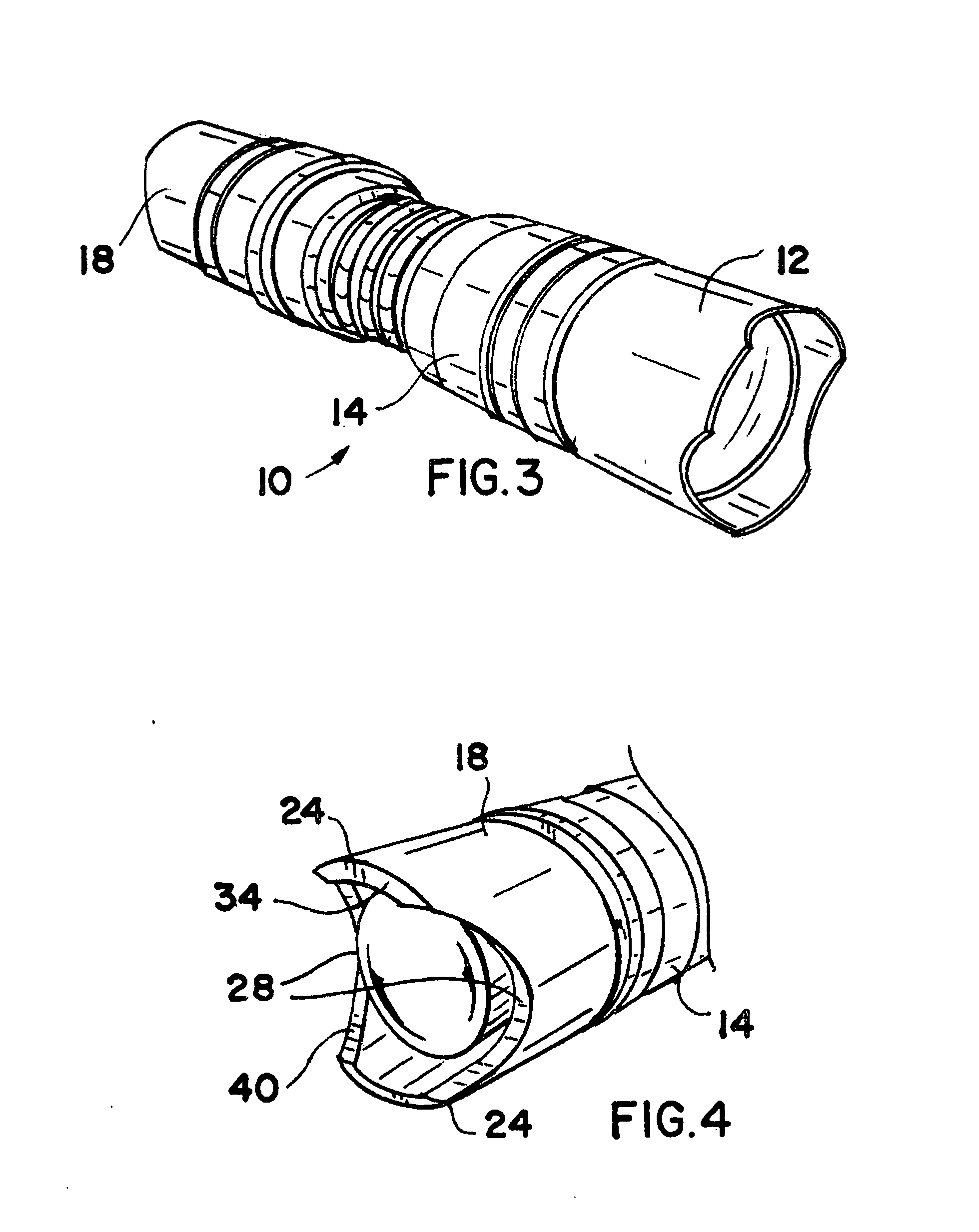
[0016]A flashlight 10 shown in FIG. 1 includes a removable front crown 12 surrounding an axially-recessed lens covering a high intensity light-emitting-diode which provides an intense beam of light. The flashlight 10 further includes a tubular body 14 for housing one or more disposable or rechargeable batteries. A removable rear end cap 18 is threaded to the rear end of the tubular body 14.
[0017]The end cap 18 includes a sidewall 20 that surrounds a user-operated switch actuator 22 which is operated by movement along flashlight axis 36. As seen in FIGS. 1 and 2, the sidewall 20 is formed with three axially-rearwardly extending wall portions 24 which are symmetrically and circumferentially separated and spaced apart by three recesses, grooves or axial cut-out portions 28.
[0018]The grooves 28 in FIGS. 1 and 2 are formed as shallow U-shaped arcuate cuts or openings in the sidewall 20. The edges 30 of each groove 28 are formed as sharp chisel edges for use in self defense. The top of ea...
PUM
 Abstract
Description
Claims
Application Information