Clear Ice Cube Tray

a clear ice cube and tray technology, applied in the field of clear ice cube tray, can solve the problems of high cost of ice cube maker, inability to use common users, and inability to freeze water drops to become clear ice cubes, etc., and achieve the effect of reducing cos

a clear ice cube and tray technology, applied in the field of clear ice cube tray, can solve the problems of high cost of ice cube maker, inability to use common users, and inability to freeze water drops to become clear ice cubes, etc., and achieve the effect of reducing cos

US20090152438A1Inactive Publication Date: 2009-06-18CHU YUE LONG

Image

  • Clear Ice Cube Tray
  • Clear Ice Cube Tray
  • Clear Ice Cube Tray

Examples


Embodiment Construction

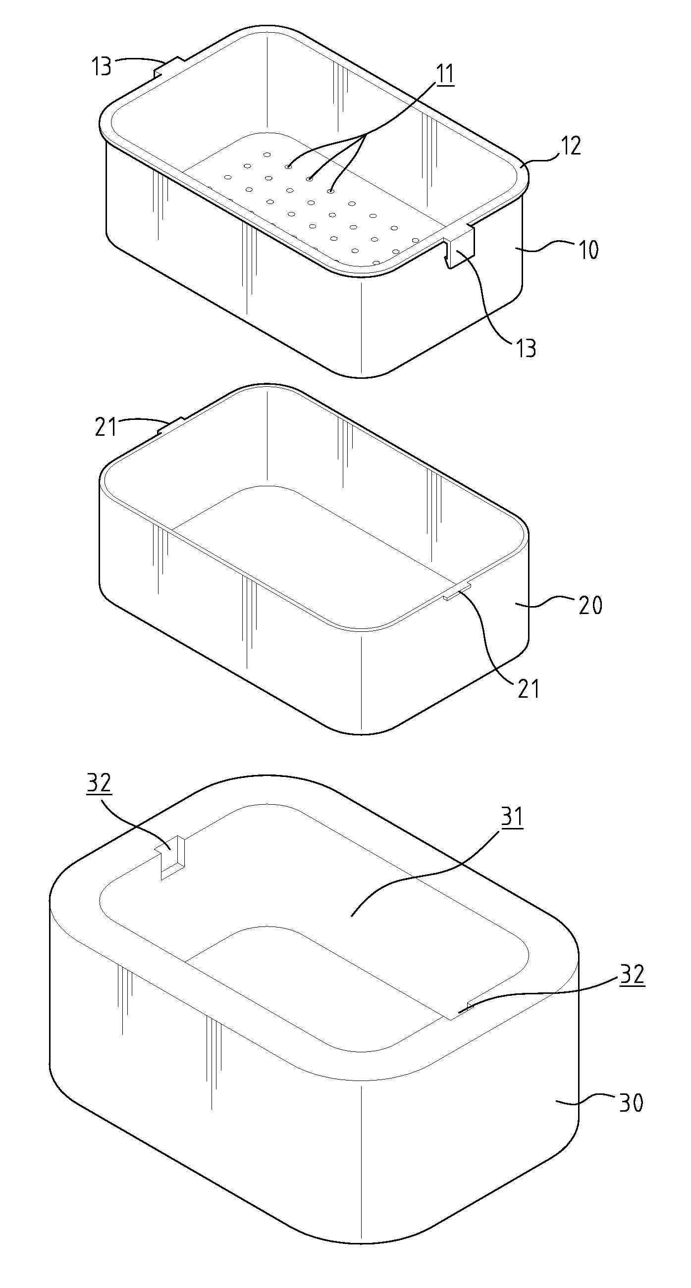
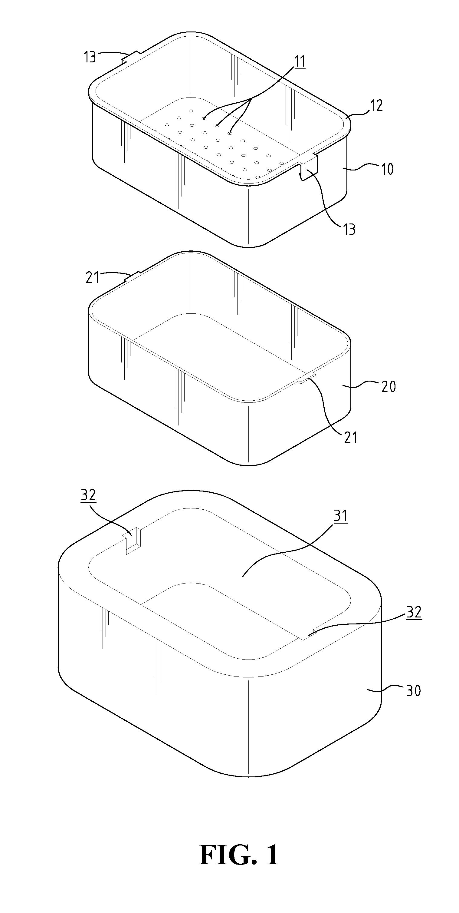
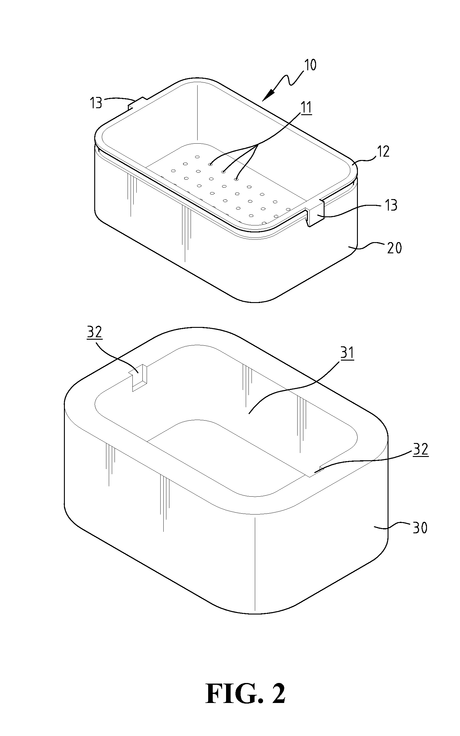
[0019]With reference to the drawings and in particular to FIGS. 1 to 4, a clear ice cube tray in accordance with the present invention comprises an inner box 10, an outer box 20 and a heat isolation housing 30.

[0020]The inner box 10 includes a plurality of holes 11 defined through a bottom thereof, and the holes 11 allow water and bubbles in the water to pass therethrough. The holes 11 can be located randomly in the bottom of the inner box 10 or separated in equal distance. The distance is preferably 20.0 mm. A diameter of each hole 11 is 4.0 mm to 6.0 mm and preferably, the diameter of each hole 11 is 50 mm. In this embodiment, a flange 12 extends outward from an open top of the inner box 10 and two hooks 13 are connected to the flange 12 formed on two opposite sides of the inner box 10. The flange 12 reinforces the strength of the inner box 10 such that when the ice is formed, the inner box 10 does not deform and the ice cube can be maintained as a desired shape.

[0021]The outer bo...


PUM

PropertyMeasurementUnit
Diameteraaaaaaaaaa
Diameteraaaaaaaaaa
Diameteraaaaaaaaaa

Abstract

A clear ice cube tray includes an inner box having a plurality of holes formed through a bottom thereof, and the inner box is received in an outer box with a gap defined between the bottom of the inner box and the inner end of the outer box. The inner box is congruent in shape with the outer box. A heat isolation housing includes a space therein for accommodating the inner box and the outer box. The water is filled in the inner box and the outer box, and frozen from a surface of water in the inner box. The bubbles in the water are then pushed into the gap through the holes so that ice cubes made in the inner box is clear.

Description

BACKGROUND OF THE INVENTION[0001]1. Field of the Invention[0002]The present invention relates generally to a clear ice cube tray which generates clear ice cubes without bubbles formed therein.[0003]2. The Prior Arts[0004]A conventional way for making ice cubes generally includes bubbles formed in the ice cubes, and because the reflection feature of the bubbles is different from the transparent ice cube, the ice cubes with bubbles appear white and not transparent.[0005]The common ice cube trays cannot remove the bubbles from the ice cubes so that the ice cubes made at home are not transparent.[0006]There is an ice cube maker that is integrated with specially designed refrigerator that is able to make clear ice cubes. However, the method is to freeze water drops to become the clear ice cubes and can only be used within special refrigerators. The ice cube maker is so costly that it is not practical for common users. The ice cube maker cannot be used with the general refrigerator design...

Claims


Application Information

Patent Timeline
18 Jun 2009
Publication
US20090152438A1
IPC
F25C1/22; F25C1/24
CPC
F25C1/24; F25C1/18
Inventors
CHU, YUE-LONG