

Angle-adjustable hinge
a technology of angle adjustment and hinge, which is applied in the field of angle adjustment of hinge, can solve the problems of spoiled furniture design, large gear portion and toothed piece protrusion, and limited attaching positions of angle adjustment hinges
- Summary
- Abstract
- Description
- Claims
- Application Information
AI Technical Summary
Problems solved by technology
Method used
Image

Examples
first embodiment
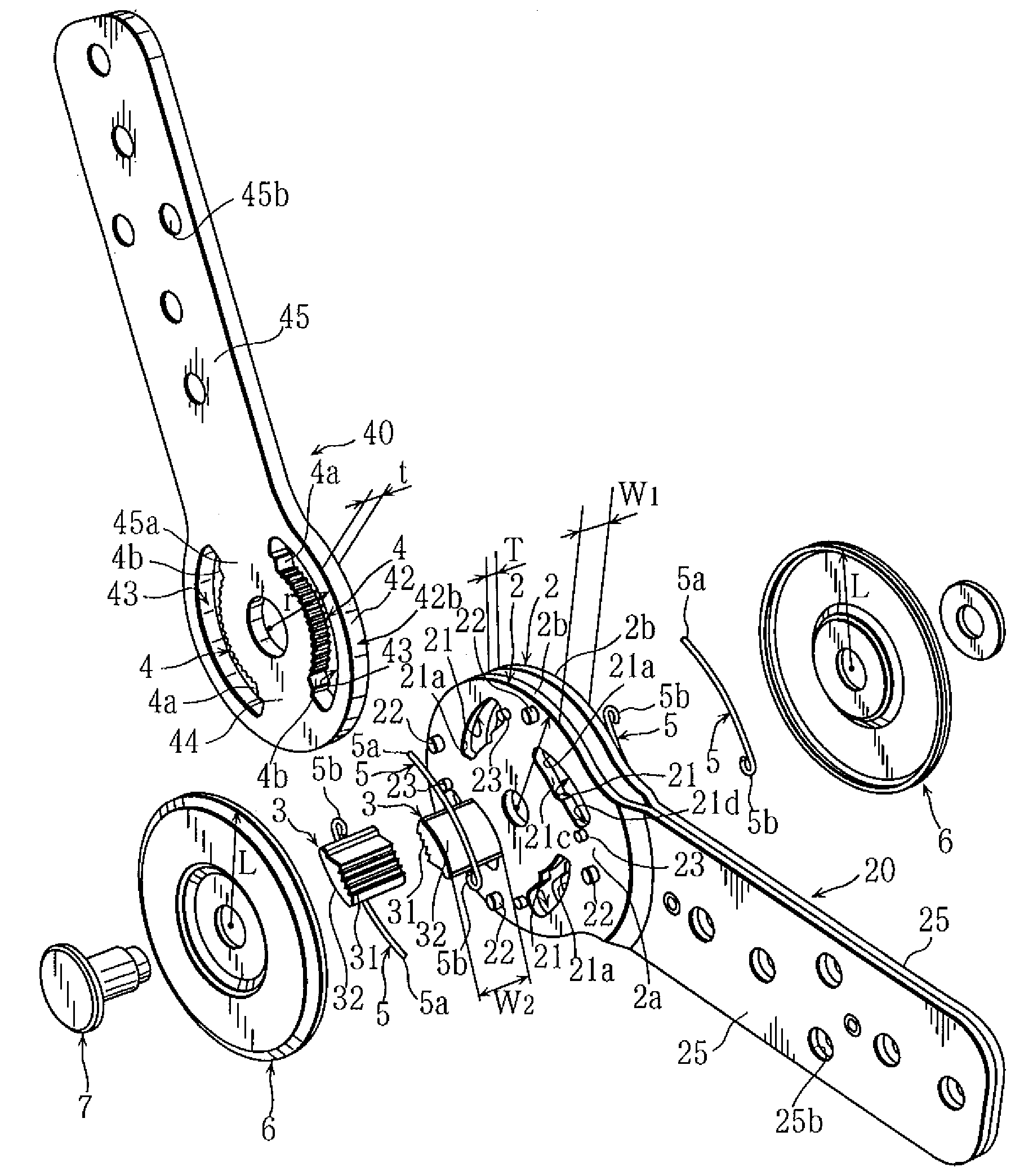
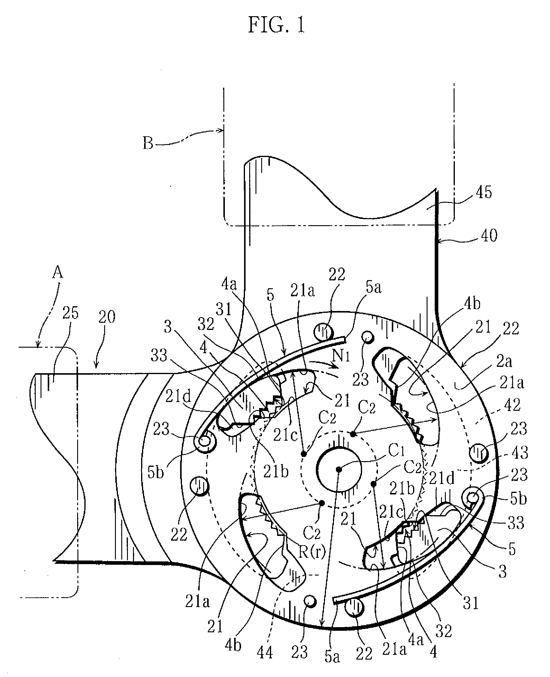
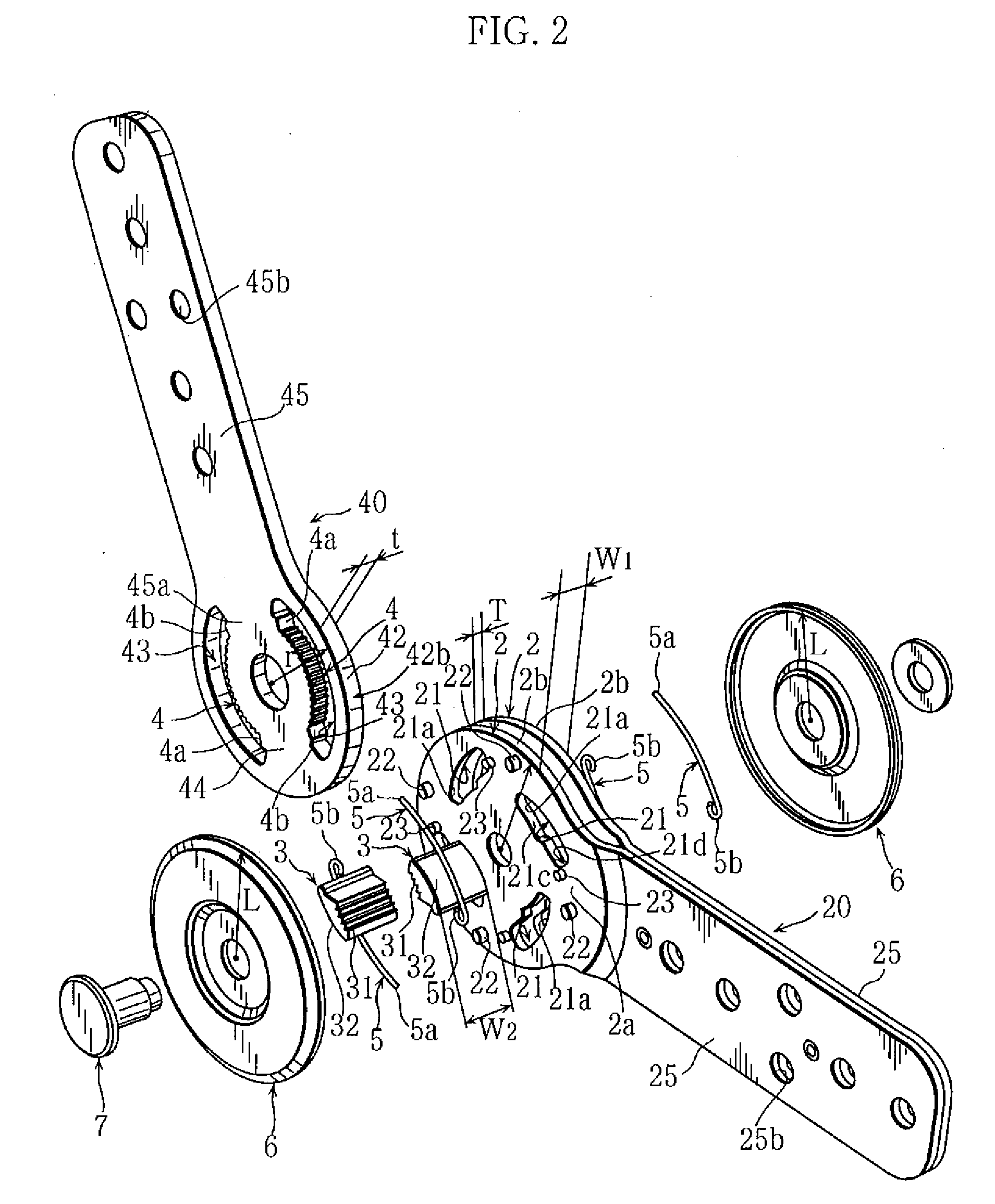
[0023]FIG. 1 is a side view of a principal portion showing an angle-adjustable hinge of the present invention. FIG. 2 is an exploded perspective view. FIG. 3 is a perspective view of an assembled state. FIG. 4 is a side view of a principal portion showing a state after an oscillation.
[0024]In the present invention, figures observed in a first axis C1 direction is called side views. And, “rotationally symmetric position of which axis of rotation is the first axis C1” may be called simply “rotationally symmetric position” for simple explanation.
[0025]The angle-adjustable hinge of the present invention is, for example, used as a hinge with which inclination angle of a back portion and armrest can be adjusted.
[0026]Other than chairs, massage chairs, headrests, footrests, etc., the hinge may be used to oscillatably connect two members such as in opening and closing doors.
[0027]In FIGS. 1 through 4, the hinge is provided with a pair of parallel wall portions 2 formed circular of which cen...
second embodiment
[0060]Next, a second embodiment is shown in FIG. 7.
[0061]The embodiment is provided with a pair of wall-portions 2, a pair of gear portions 4, and a pair of floating wedge members 3, and two wedge-shaped window portions 21 are disposed on each of the wall portions 2 on positions in rotation symmetry for 180° of which axis of symmetry is first axis C1. The floating wedge members 3 are respectively inserted to the wedge-shaped window portions 21. The wedge face 21a of the wedge-shaped window portion 21 is formed arc-shaped as to serially have the second axis C2, eccentric from the first axis C1 and rotation symmetric for every 180° around the first axis C1 as the axis of symmetry. Similar to the first embodiment, force (load) working on the gear portion 4 and the floating wedge member 3 is; supported by the pair of gear portions 4 and the pair of floating wedge members 3 disposed on the positions in rotation symmetry for 180°. Pressure is reduced by letting the floating wedge members ...
PUM
 Abstract
Description
Claims
Application Information