

Mounting apparatus for heat sink
- Summary
- Abstract
- Description
- Claims
- Application Information
AI Technical Summary
Benefits of technology
Problems solved by technology
Method used
Image

Examples
Embodiment Construction
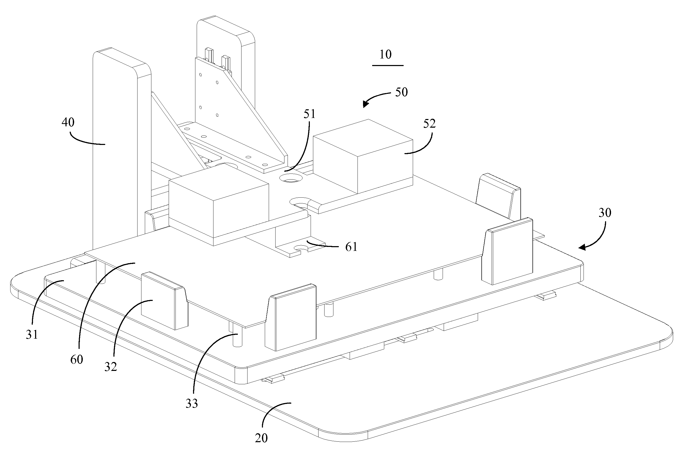
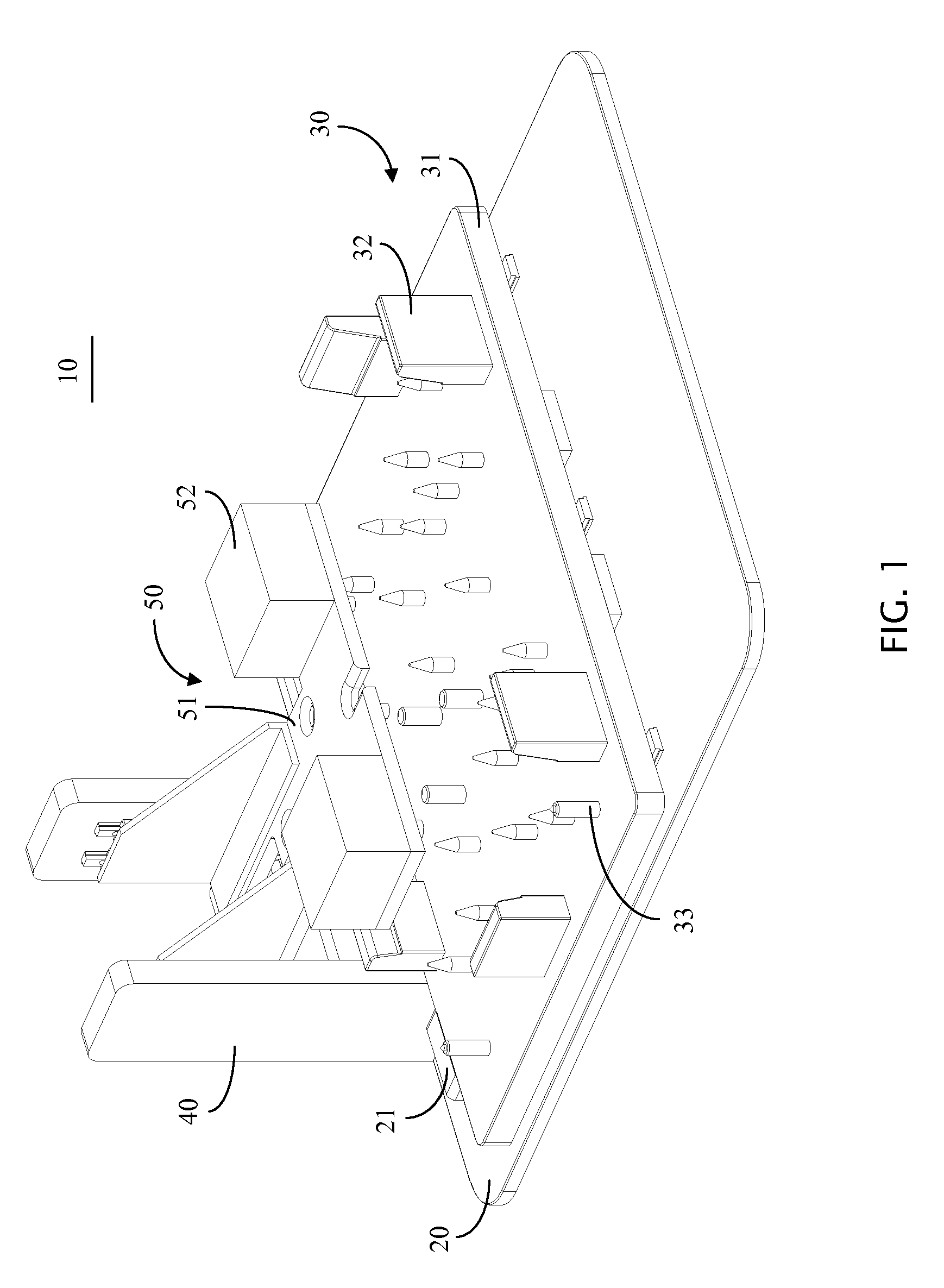
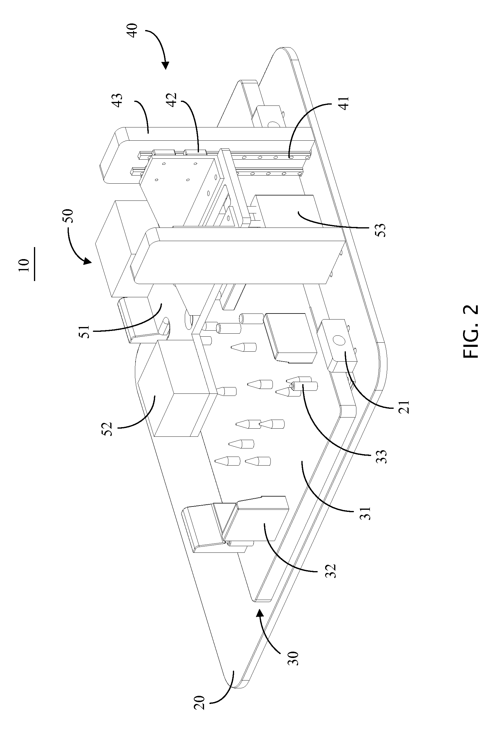
[0011]Referring to FIG. 1, a mounting apparatus 10 is disclosed. The mounting apparatus 10 includes a base 20, a load-supporting unit 30, a rack 40 mounted on the base 20, and a pressing means 50 mounted on the rack 40.
[0012]Referring to FIGS. 3 and 4, the load-supporting unit 30 includes a plate 31, a plurality of supporting means 33 for supporting a main board 60 (shown in FIG. 5), a first positioning means 32 for positioning the main board 60, and a second positioning means 34 for positioning a heat sink 61 (shown in FIG. 6). The heat sink 61 is positioned on a CPU mounted on the main board 60, but the CPU is not shown here for clarity.
[0013]In this embodiment, the supporting means 33 are rods. Some of the rods are flat on top and are configured for supporting a bottom surface of the main board 60, and the other rods are tapered and are configured for cooperating with corresponding holes defined in the main board 60. The first positioning means 32 are blocks and are positioned al...
PUM
| Property | Measurement | Unit |
|---|---|---|
| Magnetism | aaaaa | aaaaa |
Abstract
Description
Claims
Application Information