Adjustable fluid-driven illumination devices

a technology of fluid-driven illumination and adjustment, which is applied in the direction of semiconductor devices for light sources, lighting and heating equipment with built-in power, etc., can solve the problems of loss of water pressure and amount, adversely affecting fire suppression, and firefighter inability to spare extra strength or a hand to hold the flashlight for illumination of fire scenes

Active Publication Date: 2010-01-07
IND TECH RES INST
View PDF15 Cites 12 Cited by
  • Summary
  • Abstract
  • Description
  • Claims
  • Application Information

AI Technical Summary

Problems solved by technology

Accordingly, as fire-suppression equipment carried by the firefighter often weigh more than 20 Kg, the heavy flashlight disposed on the helmet causes an extra burden to the firefighter, thus adversely affecting the fire suppression.
Therefore, the firefighter cannot spare extra strength or a hand to hold the flashlight for illumination of the fire scene.
The turbine generator inlaid in the fluid passage of the fire-fighti

Method used


Image

  • Adjustable fluid-driven illumination devices
  • Adjustable fluid-driven illumination devices
  • Adjustable fluid-driven illumination devices

Examples


first embodiment

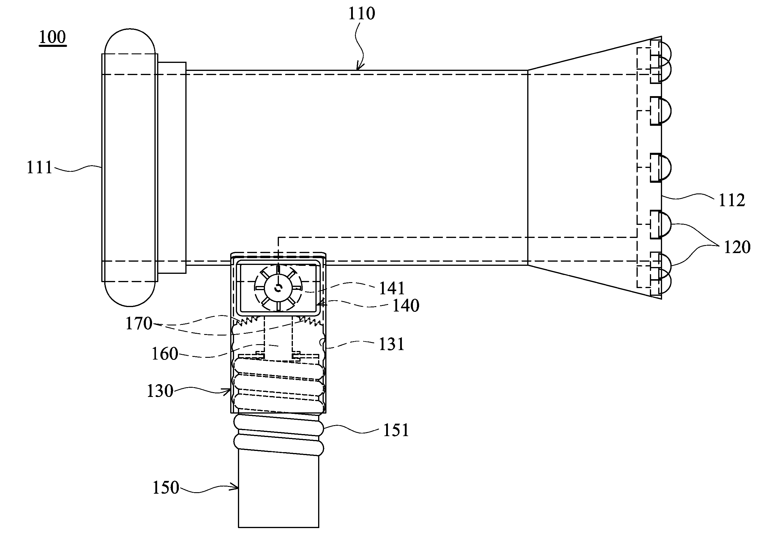
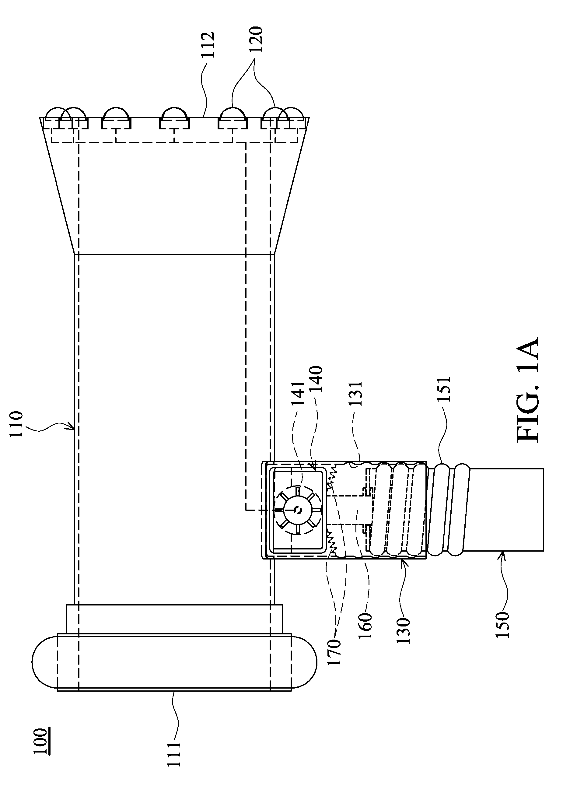
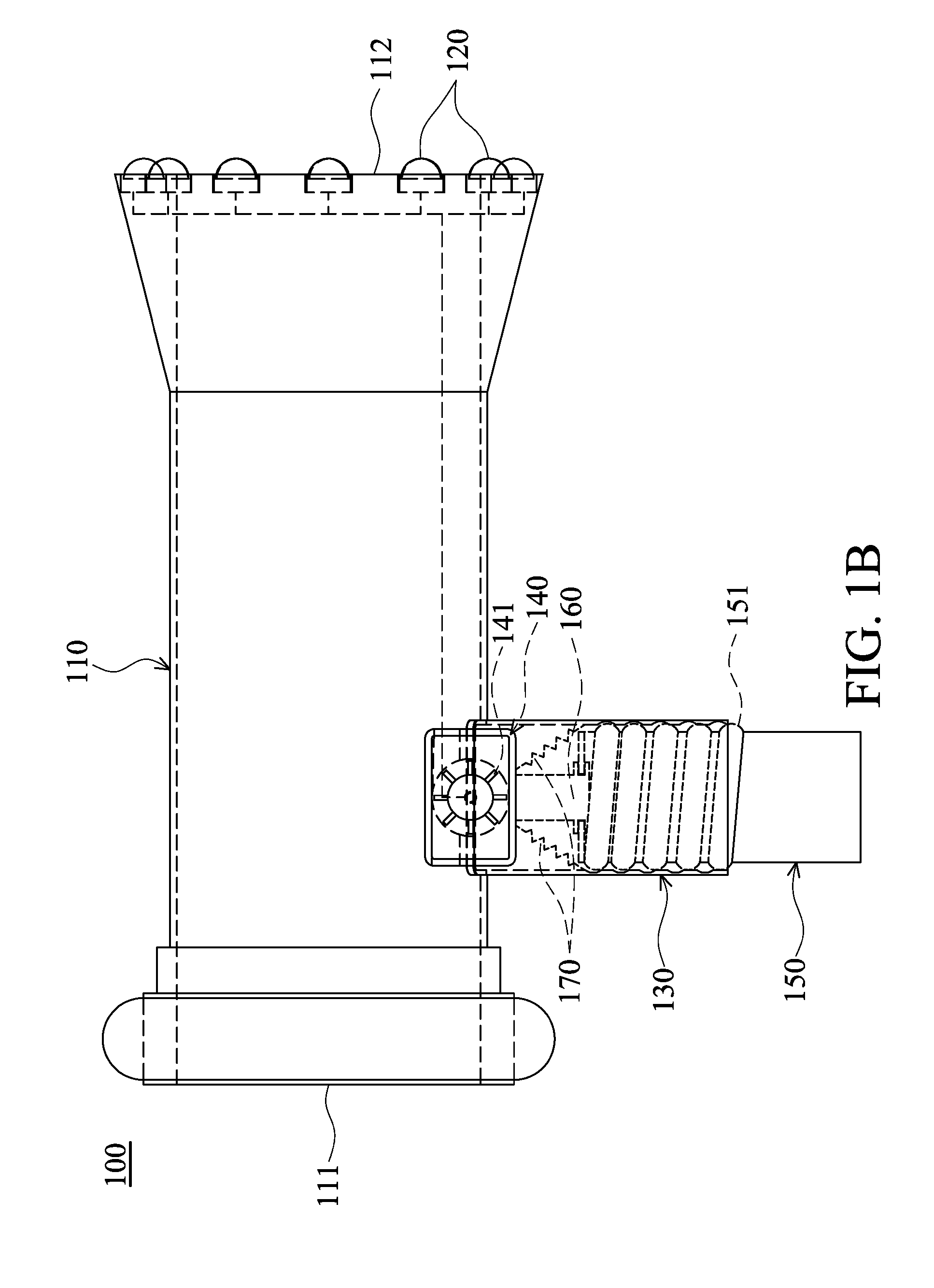
[0030]Referring to FIG. 1A and FIG. 1B, an adjustable fluid-driven illumination device 100 is applied for fire suppression and comprises a nozzle 110, a plurality of light-emitting elements 120, a grip 130, a turbine generator 140, a revolver 150, a push rod 160, and a plurality of resilient elements 170.

[0031]One end 111 of the nozzle 110 may connect to a fluid supply piping (not shown). In this embodiment, the nozzle 110 may serve as a fire-fighting nozzle.

[0032]The light-emitting elements 120 are connected to the nozzle 110. Specifically, the light-emitting elements 120 may be disposed on the other end 112 of the nozzle 110. Moreover, the light-emitting elements 120 may be high-brightness LEDs or light bulbs.

[0033]The grip 130 is connected to the nozzle 110. In this embodiment, the grip 130 is disposed between the end 111 and end 112 of the nozzle 110. Additionally, the grip 130 comprises an inner threaded portion 131.

[0034]The turbine generator 140 is electrically connected to t...

second embodiment

[0042]Referring to FIG. 2A and FIG. 2B, an adjustable fluid-driven illumination device 200 is applied for fire suppression and comprises a nozzle 210, a plurality of light-emitting elements 220, a grip 230, a turbine generator 240, a trigger 250, and a torsion spring 260.

[0043]One end 211 of the nozzle 210 may connect to a fluid supply piping (not shown). Similarly, the nozzle 210 may serve as a fire-fighting nozzle.

[0044]The light-emitting elements 220 are connected to the nozzle 210. Specifically, the light-emitting elements 220 may be disposed on the other end 212 of the nozzle 210. Moreover, the light-emitting elements 220 may be high-brightness LEDs or light bulbs.

[0045]The grip 230 is connected to the nozzle 210. In this embodiment, the grip 230 is disposed between the end 211 and end 212 of the nozzle 210.

[0046]The turbine generator 240 is electrically connected to the light-emitting elements 220 and comprises a plurality of rotating blades 241. Similarly, the rotating blades...

third embodiment

[0054]Referring to FIGS. 3A, 3B, and 3C, an adjustable fluid-driven illumination device 300 is applied for fire suppression and comprises a nozzle 310, a plurality of light-emitting elements 320, a grip 330, a turbine generator 340, a support rod 350, a fixed tube 360, a self-rotation shaft 370, a spring 380, and a button 390.

[0055]One end 311 of the nozzle 310 may connect to a fluid supply piping (not shown). Similarly, the nozzle 310 may serve as a fire-fighting nozzle.

[0056]The light-emitting elements 320 are connected to the nozzle 310. Specifically, the light-emitting elements 320 may be disposed on the other end 312 of the nozzle 310. Similarly, the light-emitting elements 320 may be high-brightness LEDs or light bulbs.

[0057]The grip 330 is connected to the nozzle 310. In this embodiment, the grip 330 is disposed between the end 311 and end 312 of the nozzle 310. Additionally, as shown in FIG. 3A and FIG. 3B, the grip 330 comprises a partition 331.

[0058]The turbine generator 3...


PUM


Abstract

An adjustable fluid-driven illumination device. At least one light-emitting element is connected to a nozzle. A grip is connected to the nozzle. A turbine generator moves between the nozzle and the grip and is electrically connected to the light-emitting element. The turbine generator includes at least one rotating blade. When moving into the nozzle to enable the rotating blade to rotate by impact of a fluid flowing through the nozzle, the turbine generator generates electric power, driving the light-emitting element to irradiate. When the turbine generator moves into the grip, the rotating blade is not subjected to the impact of the fluid flowing through the nozzle, stopping the turbine generator from generating the electric power.

Description

CROSS REFERENCE TO RELATED APPLICATIONS[0001]This application claims priority of Taiwan Patent Application No. 097124853, filed on Jul. 2, 2008, the entirety of which is incorporated by reference herein.BACKGROUND OF THE INVENTION[0002]1. Field of the Invention[0003]The invention relates to adjustable fluid-driven illumination devices, and more particularly to adjustable fluid-driven illumination devices with enhanced operational flexibility and efficiency.[0004]2. Description of the Related Art[0005]Water supply and illumination are two critical safety factors during fire suppression at a fire scene. Conventionally, in addition to holding a fire-fighting nozzle to acquire water, a firefighter utilizes a flashlight disposed on a helmet to illuminate the fire scene. Accordingly, as fire-suppression equipment carried by the firefighter often weigh more than 20 Kg, the heavy flashlight disposed on the helmet causes an extra burden to the firefighter, thus adversely affecting the fire s...

Claims


Application Information

Patent Timeline
IPC IPC(8): F21L13/02
CPCA62C31/28A62C99/009B05B3/04F03B13/00Y02B10/50F21L13/02F21S9/04F21V33/0064F21Y2101/02F05B2220/602F21Y2115/10
Inventor LIAO, JUNG-HUANG
Owner IND TECH RES INST
Why Eureka
Try Eureka