

Energy-saving controller for three-phase induction motors
- Summary
- Abstract
- Description
- Claims
- Application Information
AI Technical Summary
Benefits of technology
Problems solved by technology
Method used
Image


Examples
Embodiment Construction
[0017]The following description of certain exemplary embodiment(s) is merely exemplary in nature and is in no way intended to limit the invention, its application, or uses.
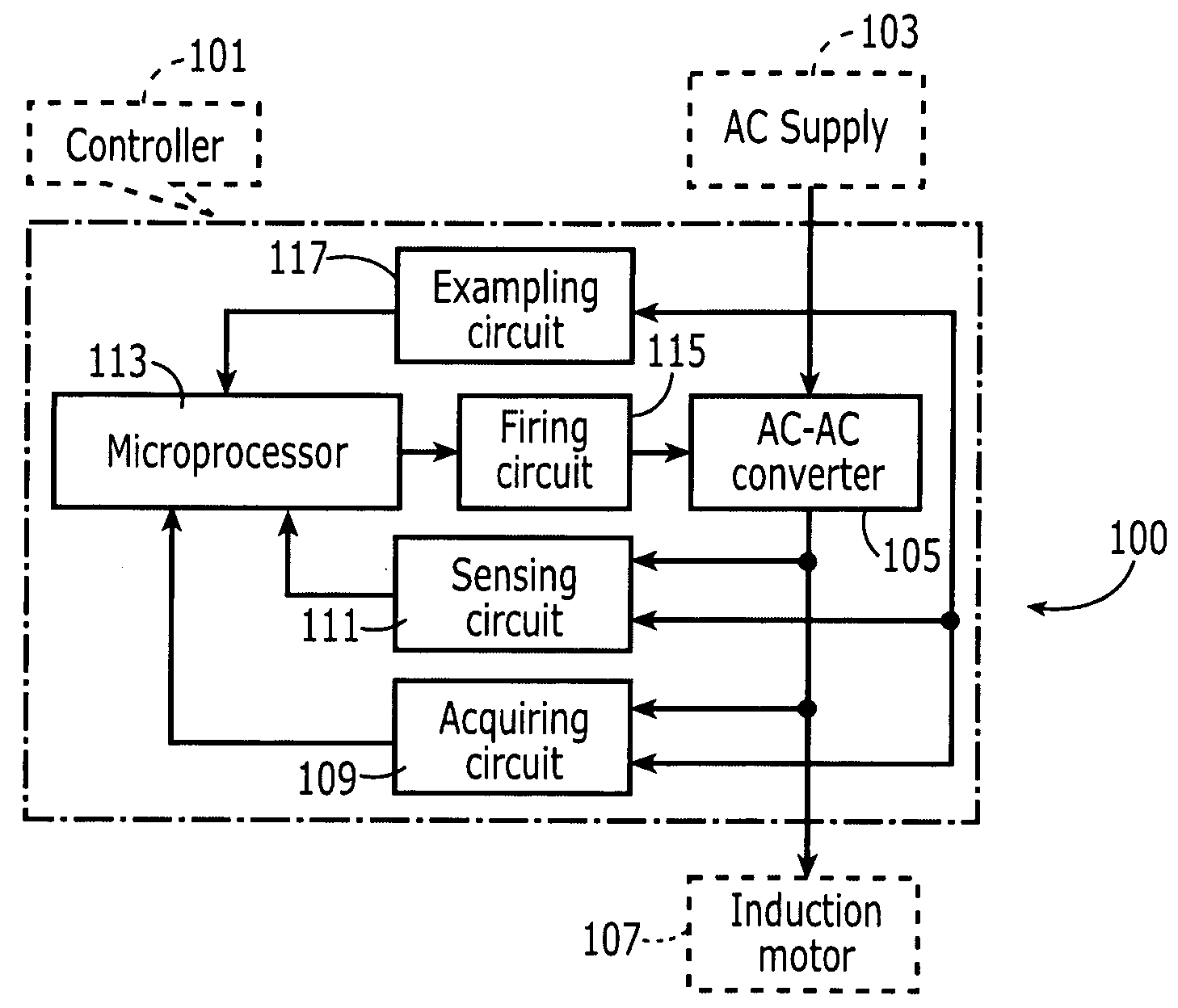
[0018]FIG. 1 is an embodiment of the system 100 of the present invention having numerous circuits, including an exampling circuit 117, a firing circuit 115, a sensing circuit 111, an acquiring circuit 109, a microprocessor 113, and an AC-AC converter 105. The controller 101 is to be used in conjunction with a power supply such as AC power supply 103, a three-phase induction motor 107. As will be discussed later, the various circuits work in conjunction with one another to successfully control the three-phase induction motor 107 in accordance with this invention.
[0019]The acquiring circuit 109 serves for acquiring the current zero-passing point, which occurs at the point where the alternation changes direction during one cycle of the current. The acquiring circuit 109 can be comprised of one or more resistors, diod...
PUM
 Abstract
Description
Claims
Application Information