Lead-through terminal

a technology of lead-through terminals and connecting bodies, which is applied in the direction of insulated conductors, contact members penetrating/cutting insulation/cable strands, and insulated conductors. it can solve the problems of time-consuming and time-consuming connection of conductors to the two screw connecting bodies, and achieves the effect of maintaining ease of installation and easy connection of conductors

Inactive Publication Date: 2011-03-31
PHOENIX CONTACT GMBH & CO KG
View PDF7 Cites 7 Cited by
  • Summary
  • Abstract
  • Description
  • Claims
  • Application Information

AI Technical Summary

Benefits of technology

[0007]Therefore, the object of this invention is to provide a lead-through terminal of the initially described type which enables easier connection of the conductors to the conductor connecting body while maintaining ease of installation.

Problems solved by technology

Even if the known lead-through terminal has proven itself very effective in practice, especially as a heavy current lead-through terminal, the connection of the conductors to the two screw connecting bodies is relatively time-consuming as a result of the connection principle of the screw terminal.

Method used


Image

  • Lead-through terminal
  • Lead-through terminal
  • Lead-through terminal

Examples


Embodiment Construction

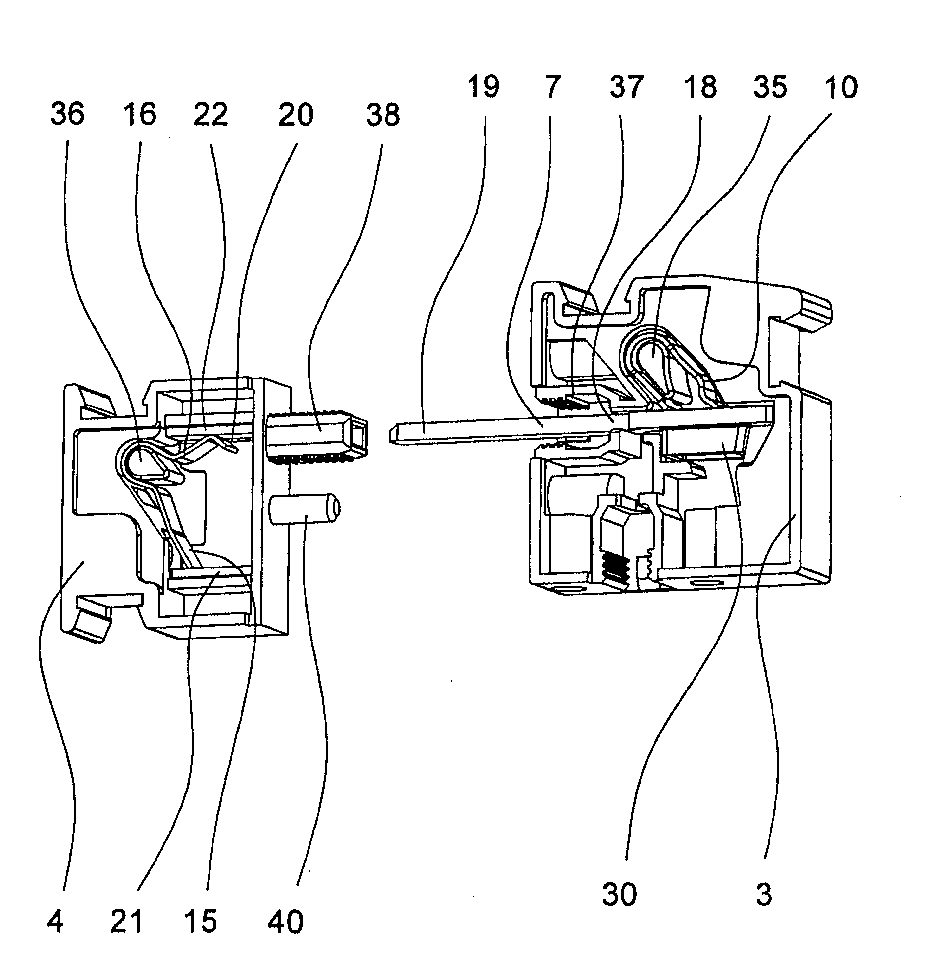
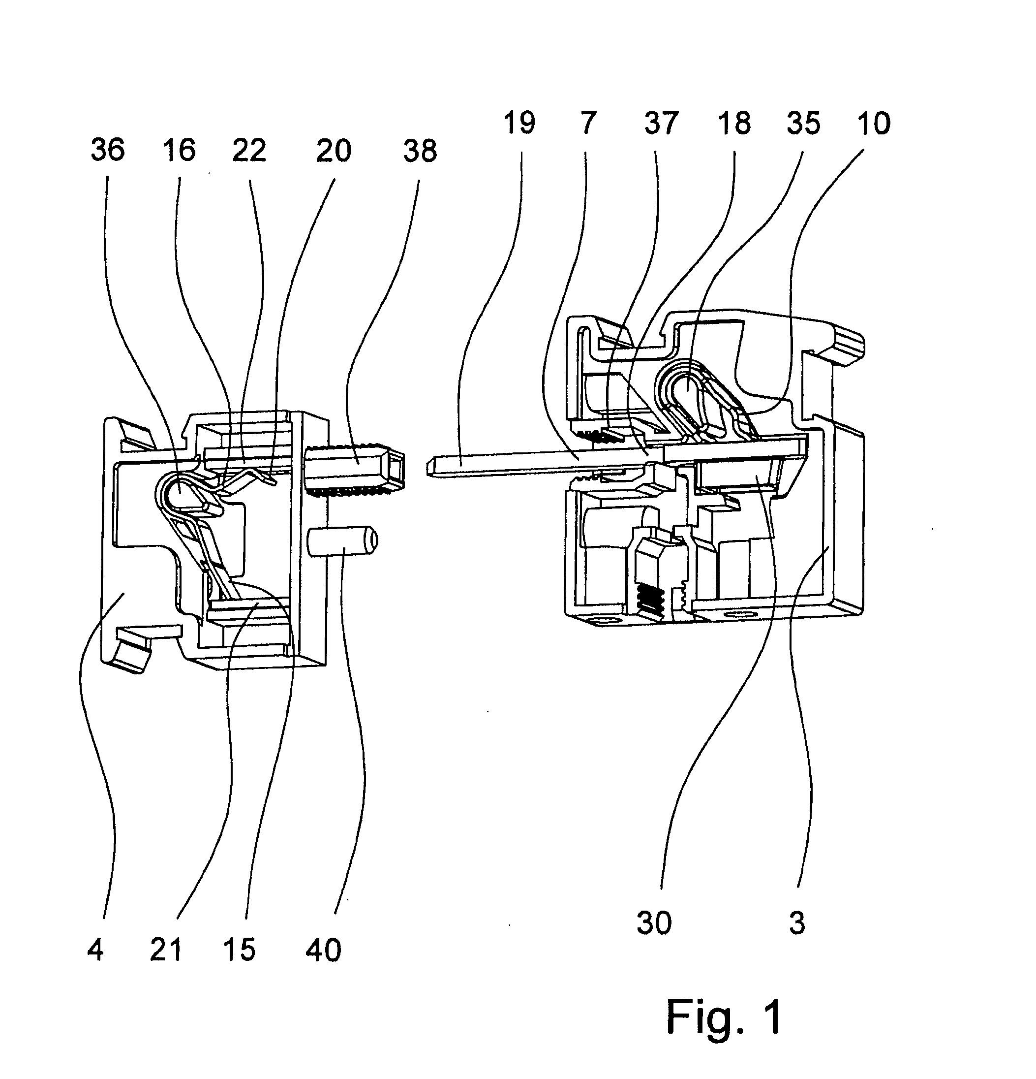
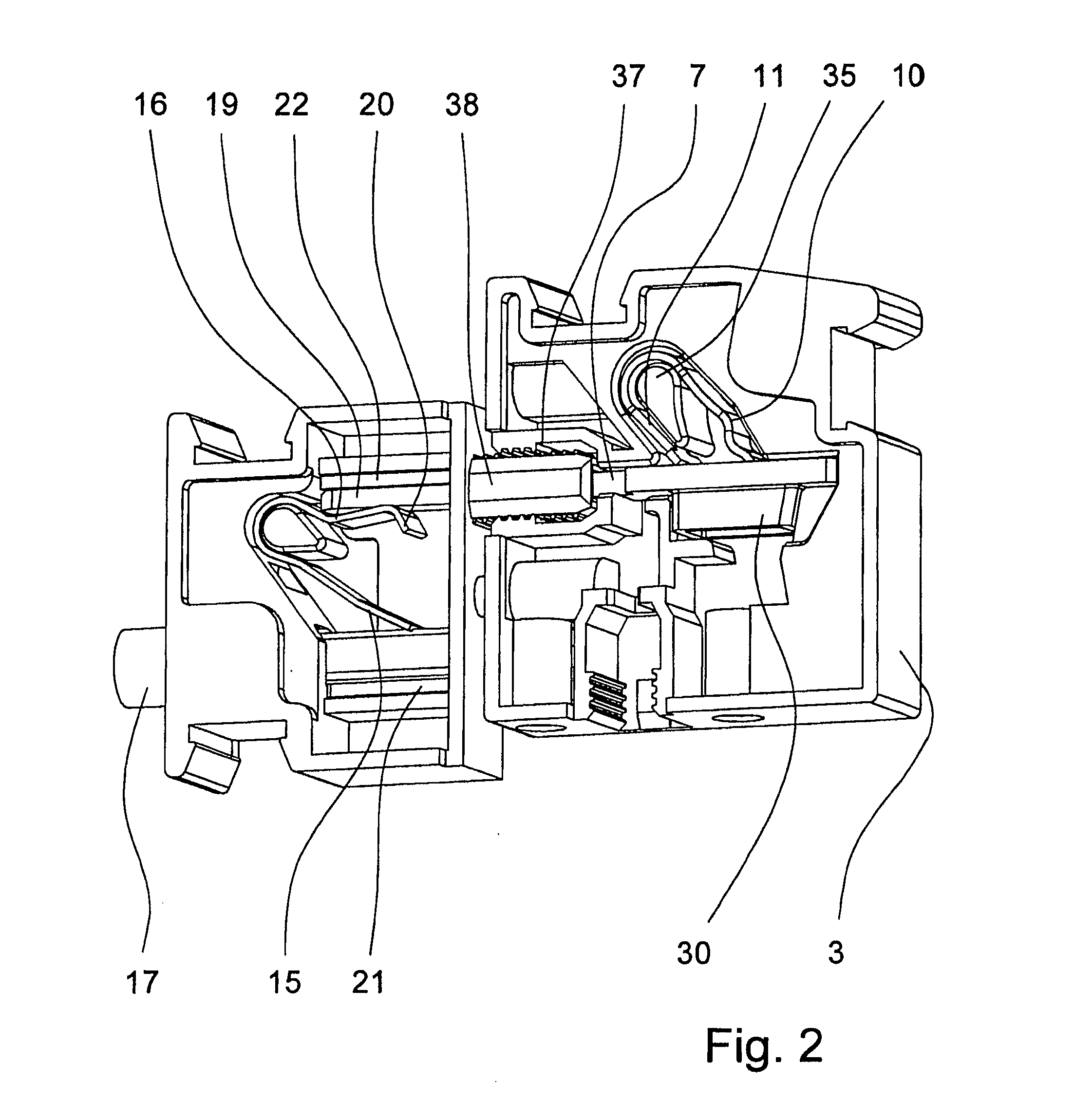
[0025]FIGS. 1 to 3 show an exemplary embodiment of a lead-through terminal 1 in accordance with the invention for routing an electrical conductor through a wall 2 which is only suggested in FIG. 3, which wall can be, for example, the wall of an electrical device. The lead-through terminal 1 is of a two-piece type so that the lead-through terminal 1 has a first terminal housing 3 and a second terminal housing 4, the first terminal housing 3 being routed through the wall 2 from one side, for example, the outside of the device, and the second terminal housing 4 being routed through the wall from the other side, for example, the inside of the device, so that the two terminal housings 3, 4, in the interlatched state, are located on the two opposing sides of the wall 2 holding the wall 2 between themselves.

[0026]Within the first terminal housing 3, there is a first conductor connecting body 5 and there is a second conductor connecting body 6 within the second terminal housing 4 (FIG. 4). ...


PUM


Abstract

A lead-through terminal for leading an electric line through a wall, having a first terminal housing and a second terminal housing, at least one first conductor connection member in the first terminal housing and at least one conductor connection member in the second terminal housing, and a bus bar electrically connecting the first conductor connection member to the second conductor connection member when the first terminal housing and the second terminal housing are connected together. The two conductor connection members each have a leg spring and a metal part, the leg springs each having a clamping leg and a contact leg, the clamping legs and corresponding metal parts each form a spring-force clamp connection for connection of an electrical conductor. The bus bar is arranged in the first terminal housing and electrically conductively connected at a first end thereof to the metal part of the first conductor connection member.

Description

BACKGROUND OF THE INVENTION[0001]1. Field of the Invention[0002]The invention relates to a lead-through terminal for routing an electrical line through a wall, with a first terminal housing and a second terminal housing, where the first terminal housing can be routed from one side and the second terminal housing from the other side to an opening formed in the wall and can be connected to one another through the opening, holding the wall between themselves, with at least one first conductor connecting body which is located in the first terminal housing and at least one second conductor connecting body which is located in the second terminal housing, and with a busbar via which the first conductor connecting body is connected to the second conductor connecting body in an electrically conductive manner, when the first terminal housing and the second terminal housing are connected to one another.[0003]2. Description of Related Art[0004]In industrial connection technology it is often nec...

Claims


Application Information

Patent Timeline
Patent Type & Authority Applications(United States)
IPC IPC(8): H02G5/06
CPCH01R13/74H01R4/4827H01R4/48275
Inventor REIBKE, HEINZ
Owner PHOENIX CONTACT GMBH & CO KG
Why Eureka
Try Eureka