Loop antenna

Active Publication Date: 2011-12-01
SAMSUNG ELECTRONICS CO LTD
View PDF4 Cites 4 Cited by
  • Summary
  • Abstract
  • Description
  • Claims
  • Application Information

AI Technical Summary

Benefits of technology

[0023]According to an aspect of another exemplary embodiment, there is provided a radio-frequency identification (RFID) short-range wireless communication device including: a loop antenna including: a substrate, an outer pattern comprising at least one loop on a surface of the substrate, and an inner pattern in an inner region of the at least one loop o

Problems solved by technology

Also, an exemplary embodiment is not required to overcome the disadvantages described a

Method used


Image

  • Loop antenna
  • Loop antenna
  • Loop antenna

Examples


Embodiment Construction

[0030]Exemplary embodiments are described in greater detail below with reference to the accompanying drawings. In the following description, like drawing reference numerals are used for like elements, even in different drawings. The matters defined in the description, such as detailed constructions and elements, are provided to assist in a comprehensive understanding of exemplary embodiments. However, an exemplary embodiment can be practiced without those specifically defined matters. Also, well-known functions or constructions are not described in detail since they would obscure the exemplary embodiments with unnecessary detail.

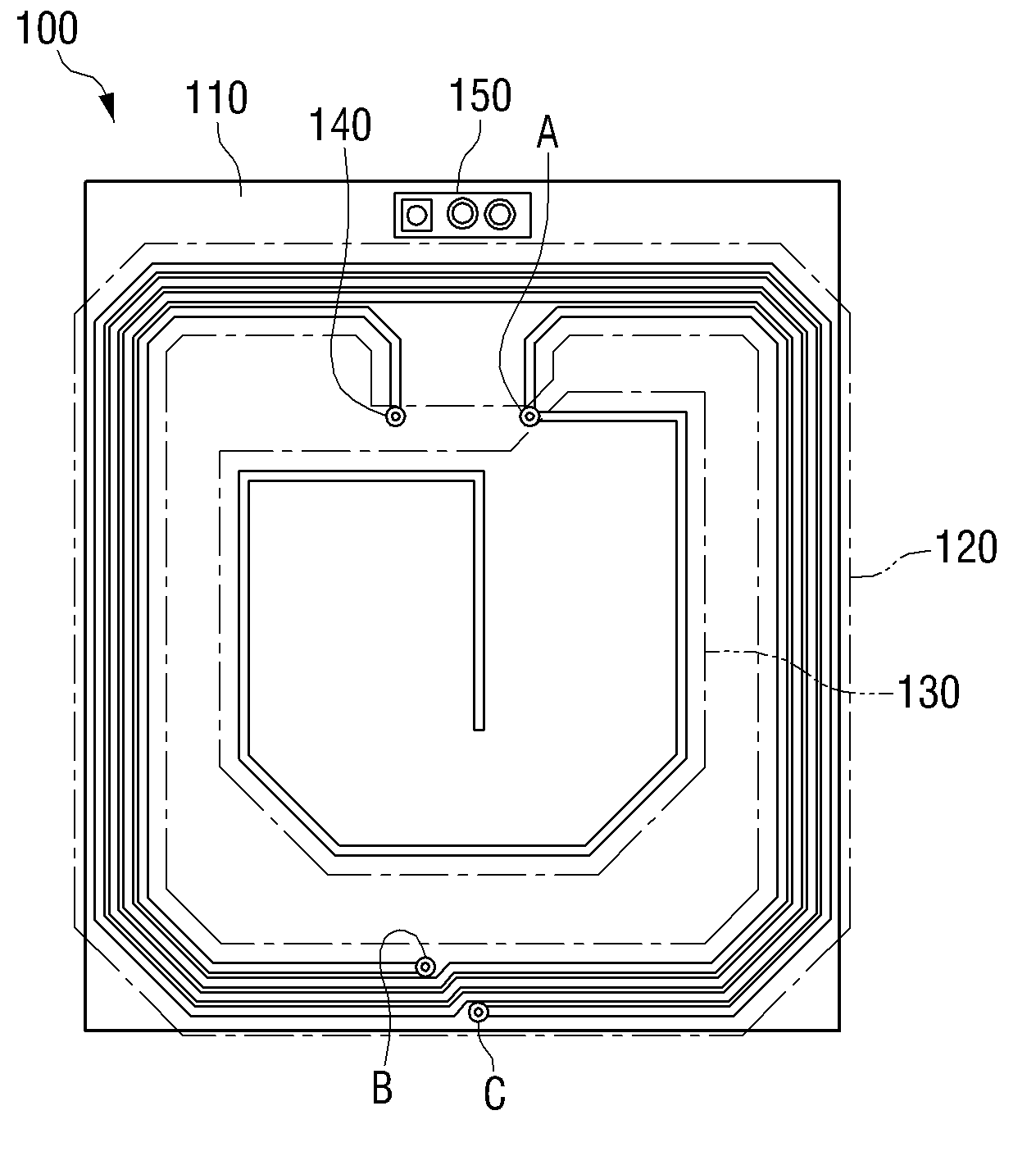
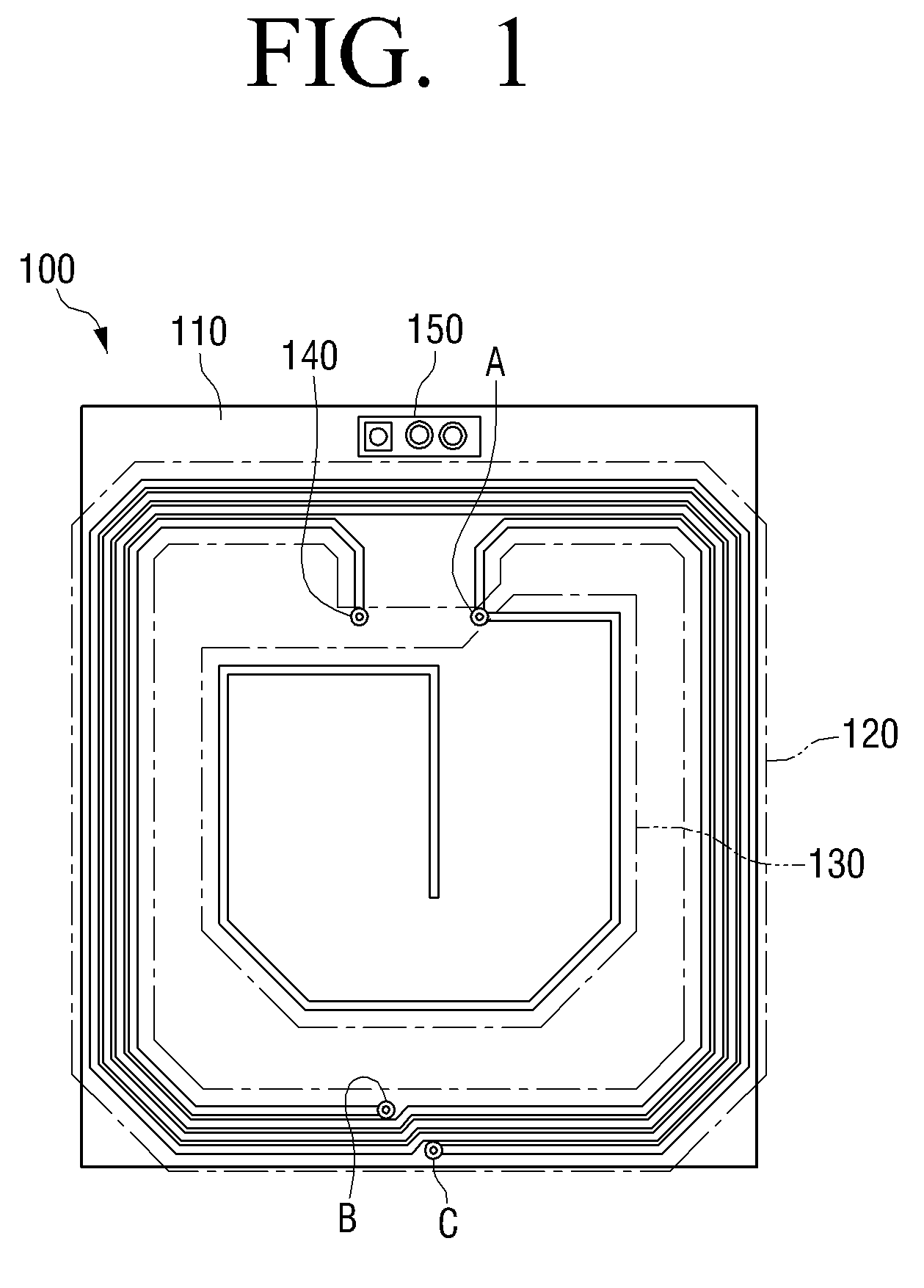
[0031]FIG. 1 is a view illustrating a loop antenna according to an exemplary embodiment. Referring to FIG. 1, the loop antenna 100 includes a substrate 110, an outer pattern 120, an inner pattern 130, a power supplying part 140, and a matching part 150.

[0032]Conductor patterns are provided on an upper surface of the substrate 110, such as the outer pattern 1...


PUM


Abstract

A loop antenna is provided. The loop antenna includes: a substrate; an outer pattern including at least one loop on a surface of the substrate; and an inner pattern in an inner region of the at least one loop of the outer pattern, an end of the inner pattern being connected to an end of the outer pattern, wherein the inner pattern is configured so that an electric current flows in the inner pattern in a direction opposite to a direction in which the electric current flows in the outer pattern. Accordingly, an H-Field characteristic of the loop antenna can be enhanced, thereby allowing the loop antenna to have a decreased size and an improved performance.

Description

CROSS-REFERENCE TO RELATED APPLICATION[0001]This application claims priority from Korean Patent Application No. 10-2010-0050170, filed on May 28, 2010 in the Korean Intellectual Property Office, the disclosure of which is incorporated herein by reference in its entirety.BACKGROUND[0002]1. Field[0003]Apparatuses and methods consistent with exemplary embodiments relate to a loop antenna. More specifically, apparatuses and methods consistent with exemplary embodiments relate to a loop antenna in which an inner pattern is formed in an inner region of an outer pattern having a loop form.[0004]2. Description of the Related Art[0005]In recent times, short-range wireless communication technologies have been variously implemented. Particularly, if a communication using radio-frequency identification (RFID), which is an example of the short-range wireless communication, is utilized, convenience of users can be improved in various fields, such as a material management, a transportation card, a...

Claims


Application Information

Patent Timeline
IPC IPC(8): H01Q7/00H01Q1/50
CPCH01Q7/00H01Q1/52
Inventor LEE, JONG-HYUCK
Owner SAMSUNG ELECTRONICS CO LTD
Why Eureka
Try Eureka