Circuit of high efficient buck-boost switching regulator and control method thereof

a switching regulator and high-efficiency technology, applied in the direction of electric variable regulation, ac network circuit arrangement, instruments, etc., can solve the problems of buck-boost converters with lower conversion efficiency, increase the driving loss of switches, and reduce efficiency, so as to improve the efficiency of non-inverted buck-boost converters

Active Publication Date: 2012-06-14
DIALOG SEMICONDUCTOR GMBH
View PDF7 Cites 59 Cited by
  • Summary
  • Abstract
  • Description
  • Claims
  • Application Information

AI Technical Summary

Benefits of technology

[0019]A principal object of the present invention is to im

Problems solved by technology

However, the lower conversion efficiency is the downside of the buck-boost converter.
This increases the driving loss of switches and lowers the efficiency.
In addition to this, the inductor current gets higher than in the buck or boost operation mode and increases the conduction loss of switches and the efficiency is further reduced.
This control method improves the efficiency compared to the classical control method, but in the buck-boost mode all four switches have to work all th

Method used


Image

  • Circuit of high efficient buck-boost switching regulator and control method thereof
  • Circuit of high efficient buck-boost switching regulator and control method thereof
  • Circuit of high efficient buck-boost switching regulator and control method thereof

Examples


Embodiment Construction

[0031]Methods and circuits to improve the efficiency of buck-boost converters are disclosed.

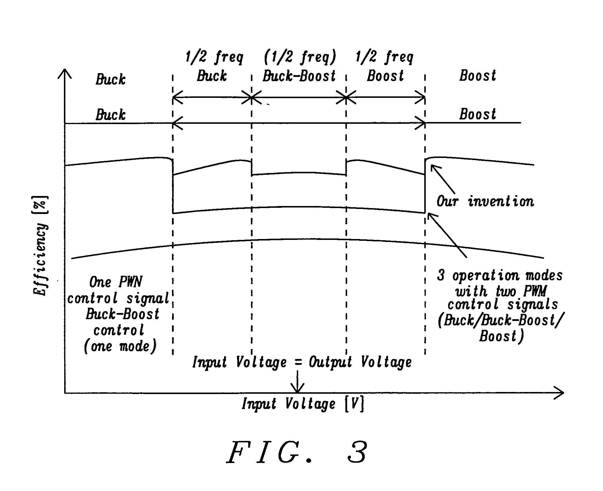
[0032]In the control method invented, the buck-boost converter operation / control can be divided into 5 modes, which are buck, half frequency buck, buck-boost, half frequency boost, and boost mode. In another embodiment of the invention the buck-boost operation could also be divided in 3 modes, which are buck and boost mode in full frequency and buck-boost mode in halved frequency. This 3-mode operation will be outlined later.

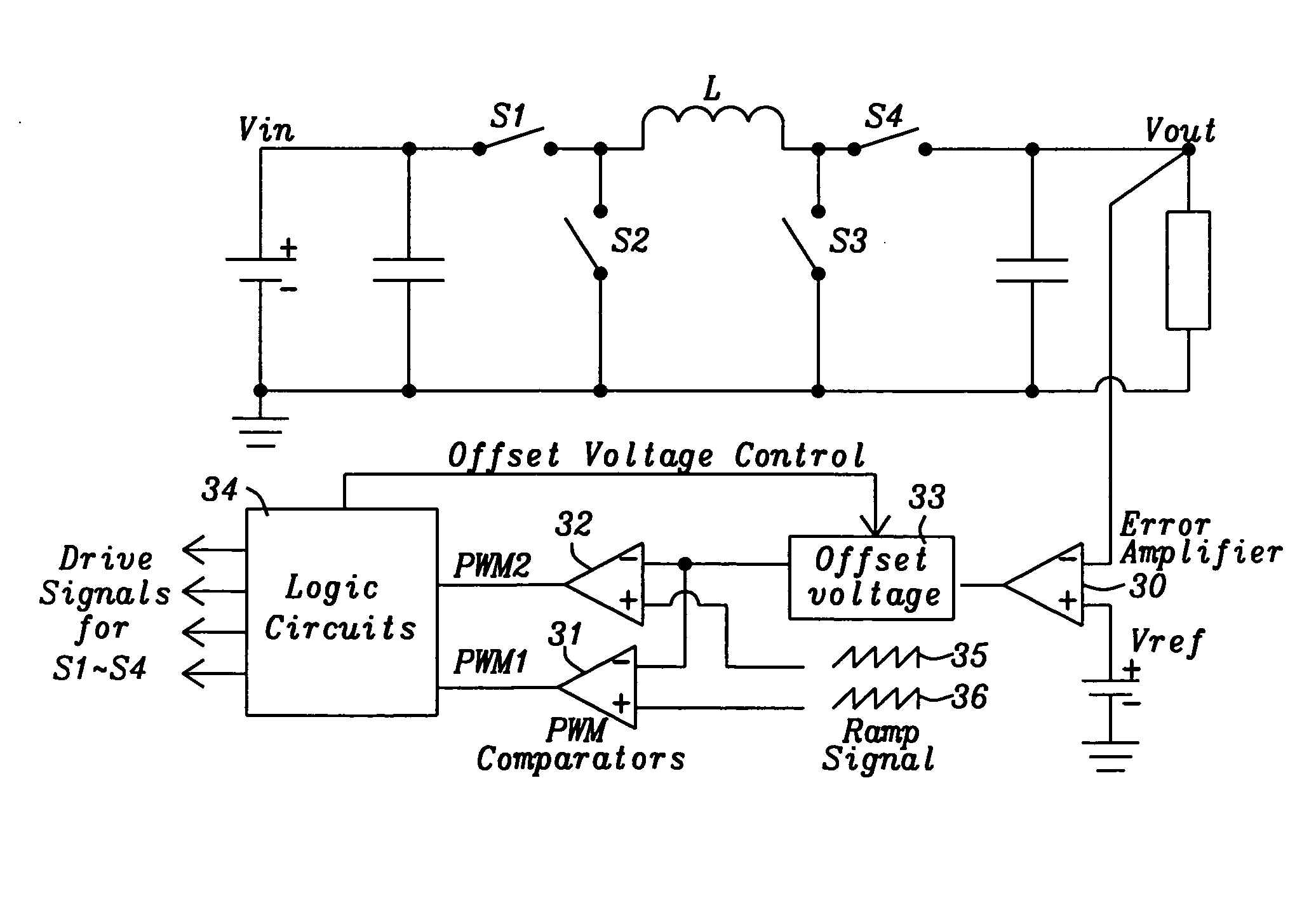
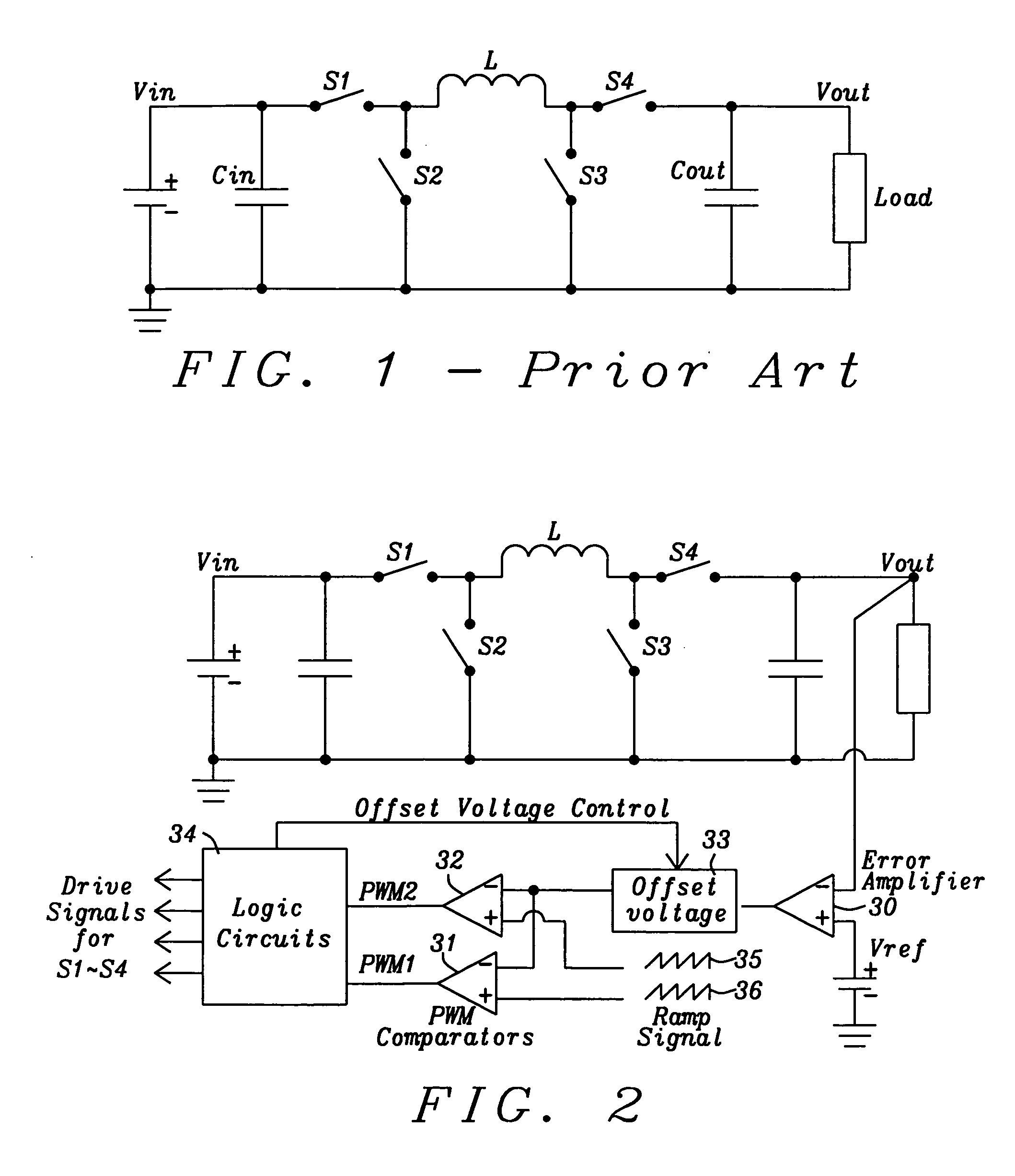
[0033]FIG. 2 illustrates a block diagram of the buck-boost converter of the present invention, which is enabled to operate in five different operation modes.

[0034]In buck and half frequency buck mode, switch S3 is continuously off and switch S4 is continuously on and this creates a buck topology. The difference between buck and half frequency buck mode is the reduced switching frequency of the half frequency buck mode. In the half frequency buck mode the converter operate...


PUM


Abstract

Systems and methods for providing a buck-boost converter with an improved efficiency are disclosed. The buck-boost converter disclosed operates in 5 different modes, namely in buck mode, half frequency buck mode, half frequency buck-boost mode, half frequency boost mode, and in boost mode. In half frequency buck mode, buck-boost mode, and in half frequency boost mode the switching frequency is halved compared to the switching frequency of buck or boost mode. A simple circuit implementation by adding two offset voltages in ramp signals or PWM comparators enables to halve the switching frequency if required.

Description

BACKGROUND[0001](1) Field of the Invention[0002]This invention relates generally to DC-to-DC converters and relates more specifically to non-inverted buck-boost switching regulators and control methods thereof.[0003](2) Description of the Prior Art[0004]The buck-boost converter is a type of DC-DC converter that has an output voltage magnitude that is either greater than or less than the input voltage magnitude. It is a switch mode power supply with a similar circuit topology to the boost converter and the buck converter. The output voltage is adjustable based on the duty cycle of the switching transistor.[0005]FIG. 1 prior art shows a non-inverted buck-boost switching regulator topology. Switches S1-S4 are usually realized by transistors.[0006]while in the On-state, S1 and S3 are closed (on) and the input voltage source is connected to the inductor L. This results in accumulating energy in L. In this stage, the capacitor Cout supplies energy to the output load.[0007]while in the Off...

Claims


Application Information

Patent Timeline
IPC IPC(8): G05F1/46
CPCH02M3/1582
Inventor KOBAYASHI, HIDENORI
Owner DIALOG SEMICONDUCTOR GMBH
Why Eureka
Try Eureka