Base station device, mobile station device, communication system, communication method, and communication program

a mobile station device and base station technology, applied in the direction of electrical equipment, synchronisation arrangements, wireless commuication services, etc., can solve problems such as communication disconnection or handover failure of mobile station devices

Inactive Publication Date: 2014-02-13
SHARP KK
View PDF6 Cites 1 Cited by
  • Summary
  • Abstract
  • Description
  • Claims
  • Application Information

AI Technical Summary

Benefits of technology

This approach enables the base station to halt or change its information without causing significant communication disruptions, ensuring continuous communication with mobile station devices by managing synchronization channel signal generation and notification.

Problems solved by technology

Accordingly, when the base station device is halted or base station device information such as the cell ID is changed, communication disconnection or handover failure occurs in the mobile station device.

Method used


Image

  • Base station device, mobile station device, communication system, communication method, and communication program
  • Base station device, mobile station device, communication system, communication method, and communication program
  • Base station device, mobile station device, communication system, communication method, and communication program

Examples


first embodiment

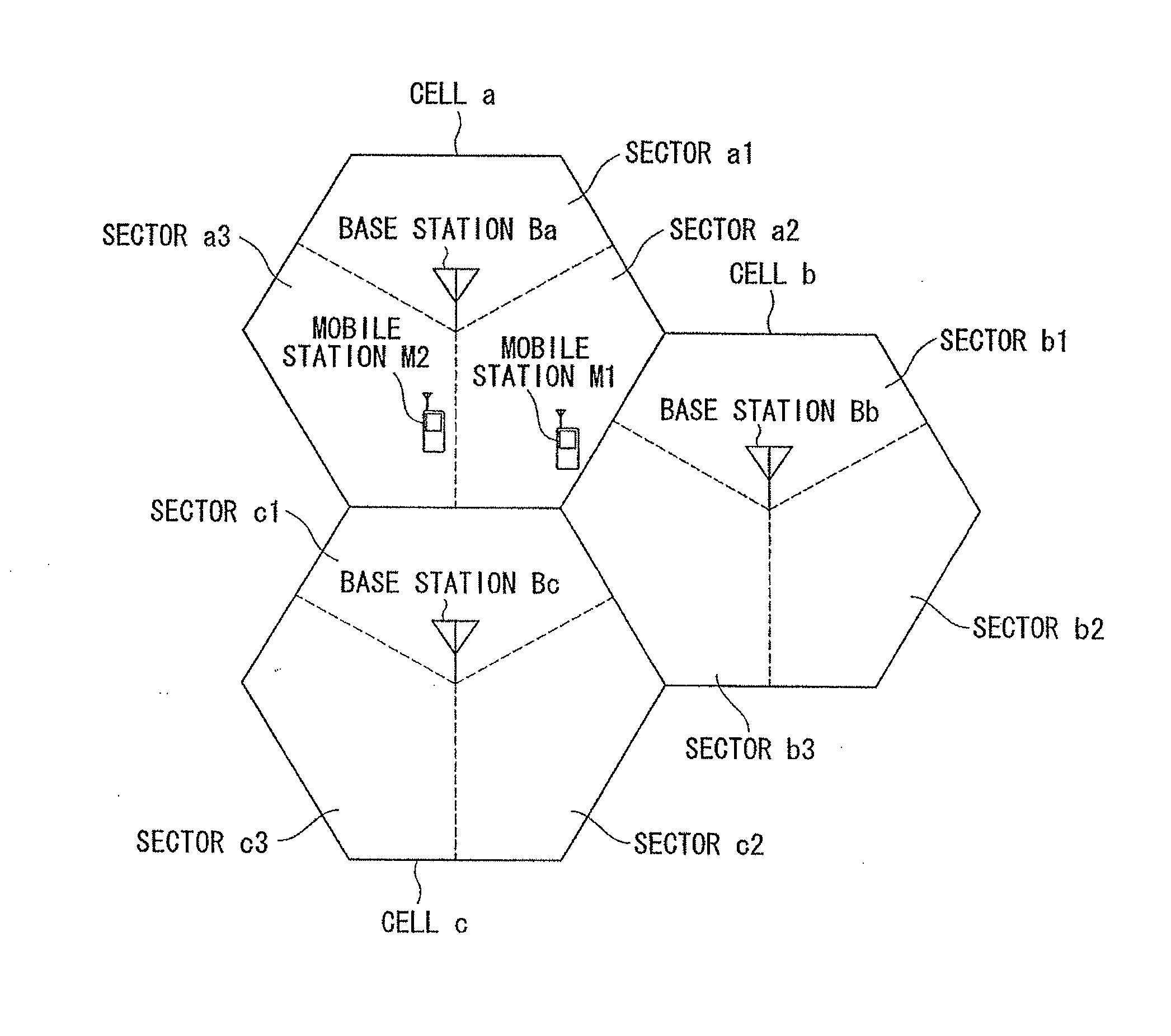
[0050]Hereinafter, embodiments of the present invention will be described in detail with reference to the accompanying drawings. FIG. 1 is a conceptual diagram showing communication areas of base station devices in the present embodiment. Base station devices Ba to Bc have cells a to c as communication coverages, respectively, and the cells a to c have three sectors a1 to a3, sectors b1 to b3, and sectors c1 to c3, respectively. However, the present invention is not limited thereto and a cell may have any number of sectors. Alternatively, a cell may not be divided into sectors.

[0051]Here, the sector a1, the sector b1, and the sector c1 are collectively referred to as sector 1 (with sector number “1”). Further, the sector a2, the sector b2, and the sector c2 are collectively referred to as sector 2 (with sector number “2”), and the sector a3, the sector b3, and the sector c3 are collectively referred to as sector 3 (with sector number “3”).

[0052]The base station devices Ba to Bc tran...

second embodiment

[0150]Hereinafter, a second embodiment of the present invention will be described in detail with reference to the accompanying drawings. In the present embodiment, a mobile station device attempting to hand over to a base station device halting transmission and reception does not hand over to the halting base station device.

[0151]Hereinafter, a base station device 300 (base station device Ba, Bb or Bc) communicating with the mobile station device 200 (mobile station device M1 or M2) will be described with reference to FIG. 12. The present embodiment differs from the first embodiment in that the second embodiment includes a different communication destination selection unit 311. However, since other components have the same functions as those in the first embodiment, a description thereof will be omitted.

[0152]The communication destination selection unit 311 selects a handover destination for the mobile station device 200, and generates a handover command corresponding to the handove...

third embodiment

[0164]Hereinafter, a third embodiment of the present invention will be described in detail with reference to the accompanying drawings. In the present embodiment, a base station device changes synchronization channel information that the base station device has. Hereinafter, an example in which a PSC or an SSC is changed will be described. However, the present embodiment is not limited thereto, and the PSC and the SSC may be simultaneously changed or other information may be changed.

[0165]Hereinafter, a base station device 400 (base station device Ba, Bb or Bc) communicating with a mobile station device 500 (mobile station device M1 or M2) will be described with reference to FIG. 14. The present embodiment differs from the second embodiment in that the third embodiment includes a different network control unit 410 and a different radio control unit 420. However, since other components have the same functions as those in the first embodiment, a description thereof will be omitted.

[01...


PUM


Abstract

A base station (BS) that changes a state of the BS from a first state to a second state, wherein the first state being a state in which a sector of the BS is not switched off, transmission from the BS to the sector is able to be received by mobile station devices, and the BS is able to communicate with the mobile station devices in the sector, and the second state being a state in which the sector is switched off, transmission from the BS to the sector is unable to be received by the mobile station device being able to communicate with the BS on the first state device in the sector, the BS is unable to communicate with the mobile station devices being able to communicate with the BS on the first state in the sector and handover into the sector is unable to be performed.

Description

[0001]This application is a Divisional of U.S. application Ser. No. 12 / 865,038, filed on Jul. 28, 2010. U.S. application Ser. No. 12 / 865,038 is the national phase of PCT International Application No. PCT / JP2009 / 051207, filed on Jan. 26, 2009, which claims priority to and the benefits of Japanese Patent Application No. 2008-020878 filed on Jan. 31, 2008, the disclosure of which are incorporated herein by reference in their entireties.TECHNICAL FIELD[0002]The present invention relates to a base station device, a mobile station device, a communication system, a communication method, and a communication program.BACKGROUND ART[0003]In recent years, as some techniques considered for fourth-generation mobile communication systems have been introduced to third-generation mobile communication systems, evolved universal terrestrial radio access (hereinafter, referred to as EUTRA) aiming at high-speed communication has been considered by a standardization group, the 3rd Generation Partnership ...

Claims


Application Information

Patent Timeline
Patent Type & AuthorityApplications(United States)
IPC IPC(8): H04W24/02
CPCH04W24/02H04W24/04H04W56/0025H04W56/001H04W92/10
InventorTSUBOI, HIDEKAZUUEMURA, KATSUNARI
OwnerSHARP KK