Shift member fixing structure of electrical connection terminal

Active Publication Date: 2016-07-14
SWITCHLAB +1
View PDF3 Cites 25 Cited by
  • Summary
  • Abstract
  • Description
  • Claims
  • Application Information

AI Technical Summary

Benefits of technology

[0014]It is therefore a primary object of the present invention to provide a shift member fixing structure of electrical connection terminal includes an assembly of a terminal and a shift member to improve the shortcoming of the conventional terminal that the structure is complicated and the manufacturing cost is higher. The terminal includes a main body defining a chamber and a metal leaf spring disposed in the chamber for pressing a conductive wire into electrical connection or releasing the conductive wire in response to the operation of the shift member. A predetermined section of the shift member is formed with an

Problems solved by technology

Obviously, this structural form will increase the complexity in manufacturing of the metal leaf spring and make the manu

Method used


Image

  • Shift member fixing structure of electrical connection terminal
  • Shift member fixing structure of electrical connection terminal
  • Shift member fixing structure of electrical connection terminal

Examples


Embodiment Construction

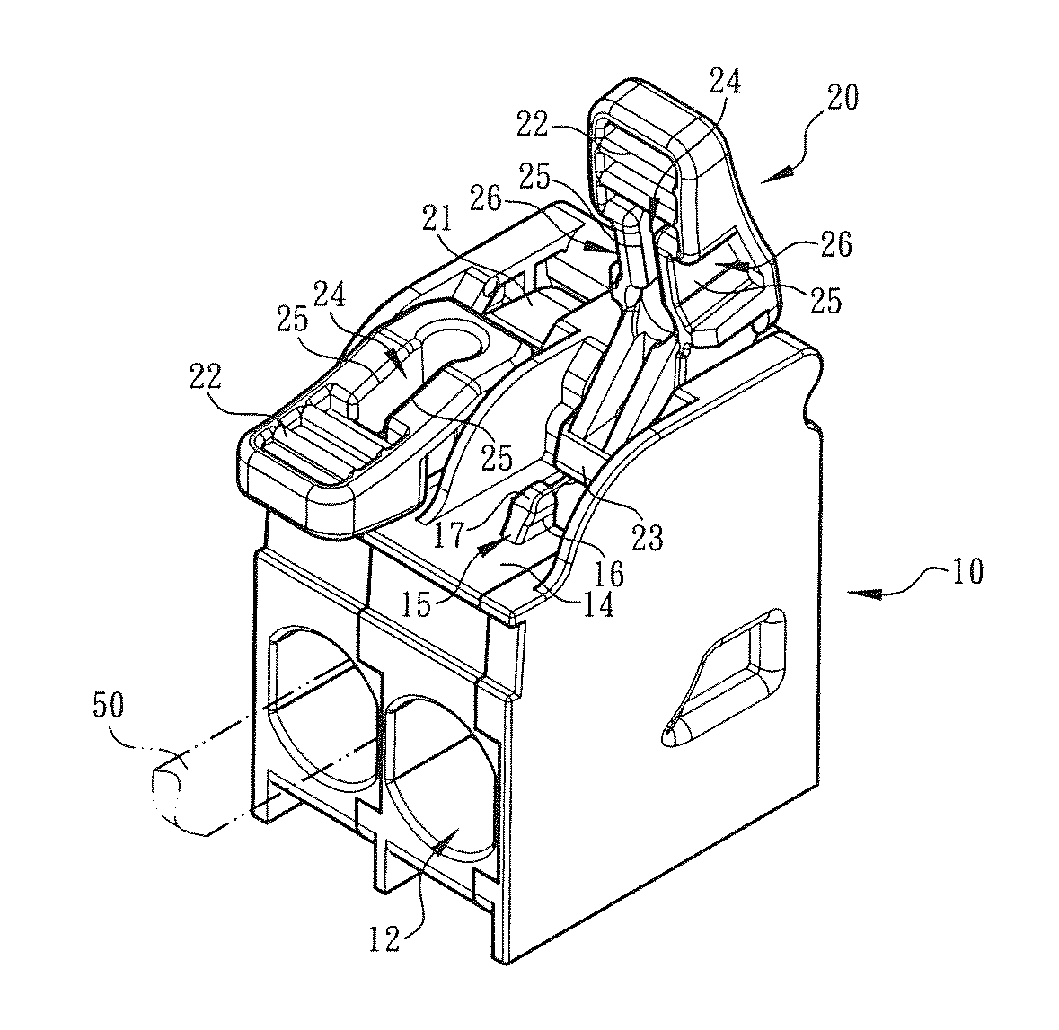
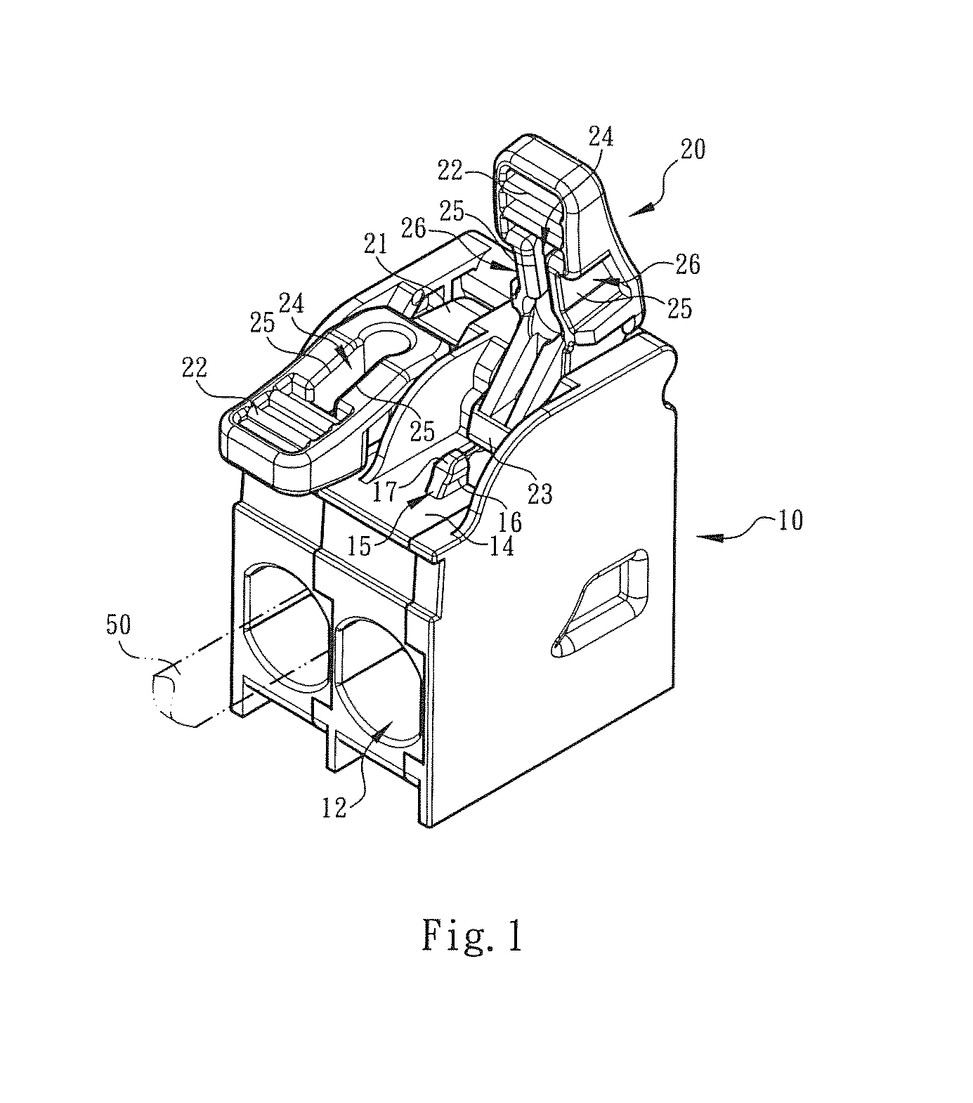
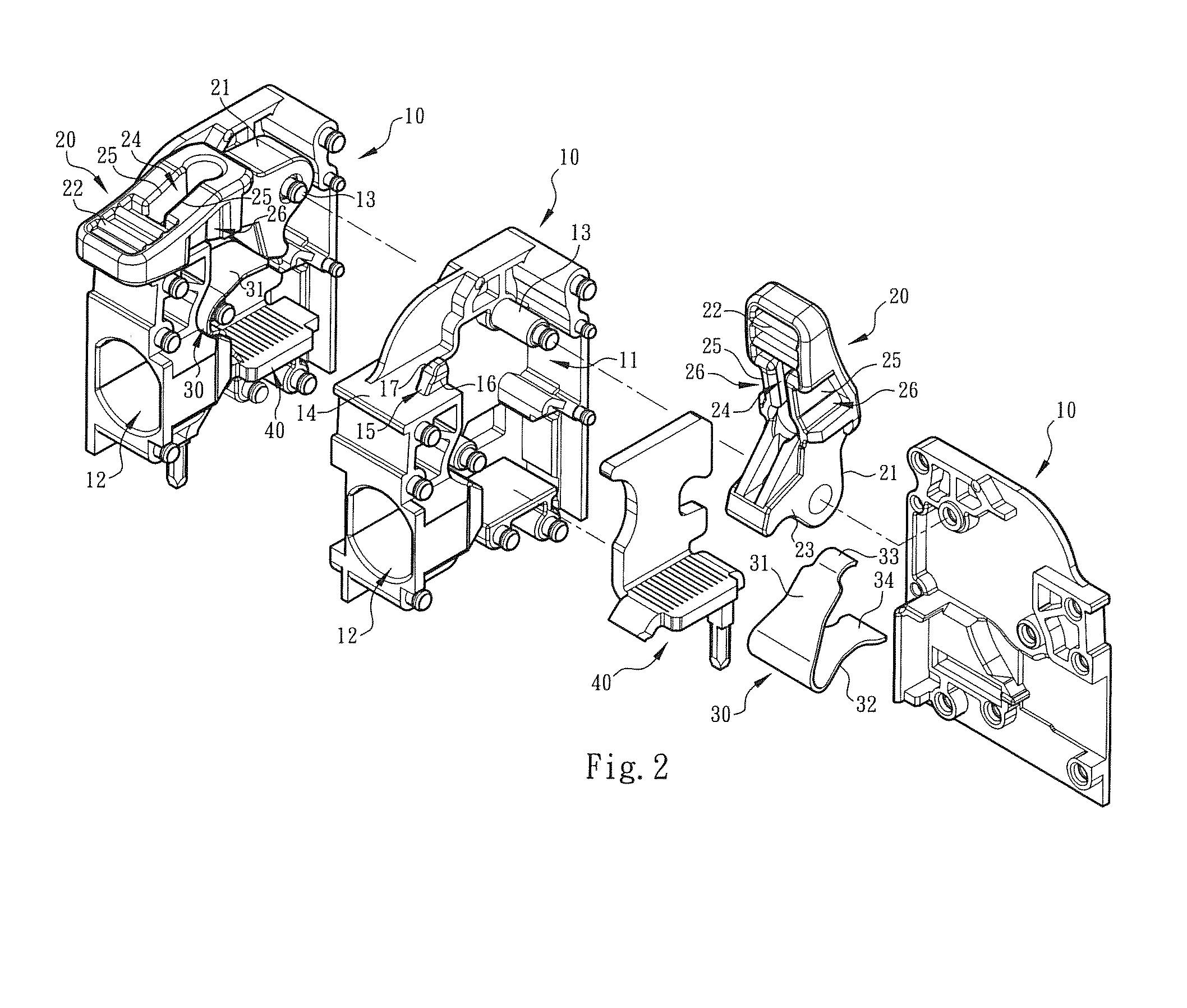
[0023]Please refer to FIGS. 1, 2 and 3. The shift member fixing structure of electrical connection terminal of the present invention includes a main body 10 made of insulation material and a shift member 20. The main body 10 defines a cavity 11. A metal leaf spring 30 and a terminal pin 40 are mounted in the chamber 11. The terminal pin 40 is for inserting on a circuit board (such as a PCB). The main body 10 includes a wire inlet 12 in communication with the chamber 11. A conductive wire 50 can be inserted into the chamber 11 through the wire let 12 to be pressed by the metal leaf spring 30, whereby the conductive wire 50 is electrically connected with the terminal pin 40.

[0024]In this embodiment, the metal leaf spring 30 is movable along with the motion of the shift member 20 to press the conductive wire 50 into electrical connection with the terminal pin 40 or release the conductive wire 50. To speak more specifically, the shift member 20 includes a pivoted end 21 and an operation...


PUM


Abstract

A shift member fixing structure of electrical connection terminal includes an assembly of a terminal and a shift member to improve the shortcoming of the conventional terminal that the structure is complicated and the manufacturing cost is higher. The terminal includes a main body defining a chamber and a metal leaf spring disposed in the chamber for pressing a conductive wire or releasing the conductive wire in response to the operation of the shift member. A predetermined section of the shift member is formed with an insertion section and walls defining the insertion section. A part of the wall is removed to provide elastic effect for the insertion section. The removed part is repositioned on a surface of upper section of the main body to form an interference section. After the shift member is pressed down, the interference section is assembled with the insertion section.

Description

BACKGROUND OF THE INVENTION[0001]1. Field of the Invention[0002]The present invention relates generally to a shift member fixing structure of electrical connection terminal, and more particularly to a terminal device for an electrical conductive wire to insert and connect with. The shift member is formed with an insertion section and walls defining the insertion section. Apart of the wall is removed to provide elastic effect for the insertion section. The removed part is repositioned on a surface of the main body to form an interference section. The insertion section and the interference section together set up a fixing system. Only when an operational force is applied to the shift member to release the shift member from the assembling or interference state, the shift member can be further moved. The shift member fixing structure of electrical connection terminal can be easily and conveniently operated.[0003]2. Description of the Related Art[0004]A conventional connection terminal (...

Claims


Application Information

Patent Timeline
IPC IPC(8): H01R4/48
CPCH01R4/4809H01R13/62955H01R4/48365
Inventor WU, CHIH-YUANCHEN, WEI-CHI
Owner SWITCHLAB
Why Eureka
Try Eureka