Vehicle airbag system

a technology for airbags and vehicles, applied in the direction of vehicular safety arrangments, vehicle components, pedestrian/occupant safety arrangements, etc., to achieve the effect of excellent advantageous

Active Publication Date: 2016-10-13
TOYOTA JIDOSHA KK
View PDF2 Cites 15 Cited by
  • Summary
  • Abstract
  • Description
  • Claims
  • Application Information

AI Technical Summary

Benefits of technology

[0027]The vehicle airbag system according to the present invention as explained above has an excellent advantageous effect of enabling rot

Problems solved by technology

However, there is a concern that, when the head of the occupant moving obliquely forward in an oblique

Method used


Image

  • Vehicle airbag system
  • Vehicle airbag system
  • Vehicle airbag system

Examples


Embodiment Construction

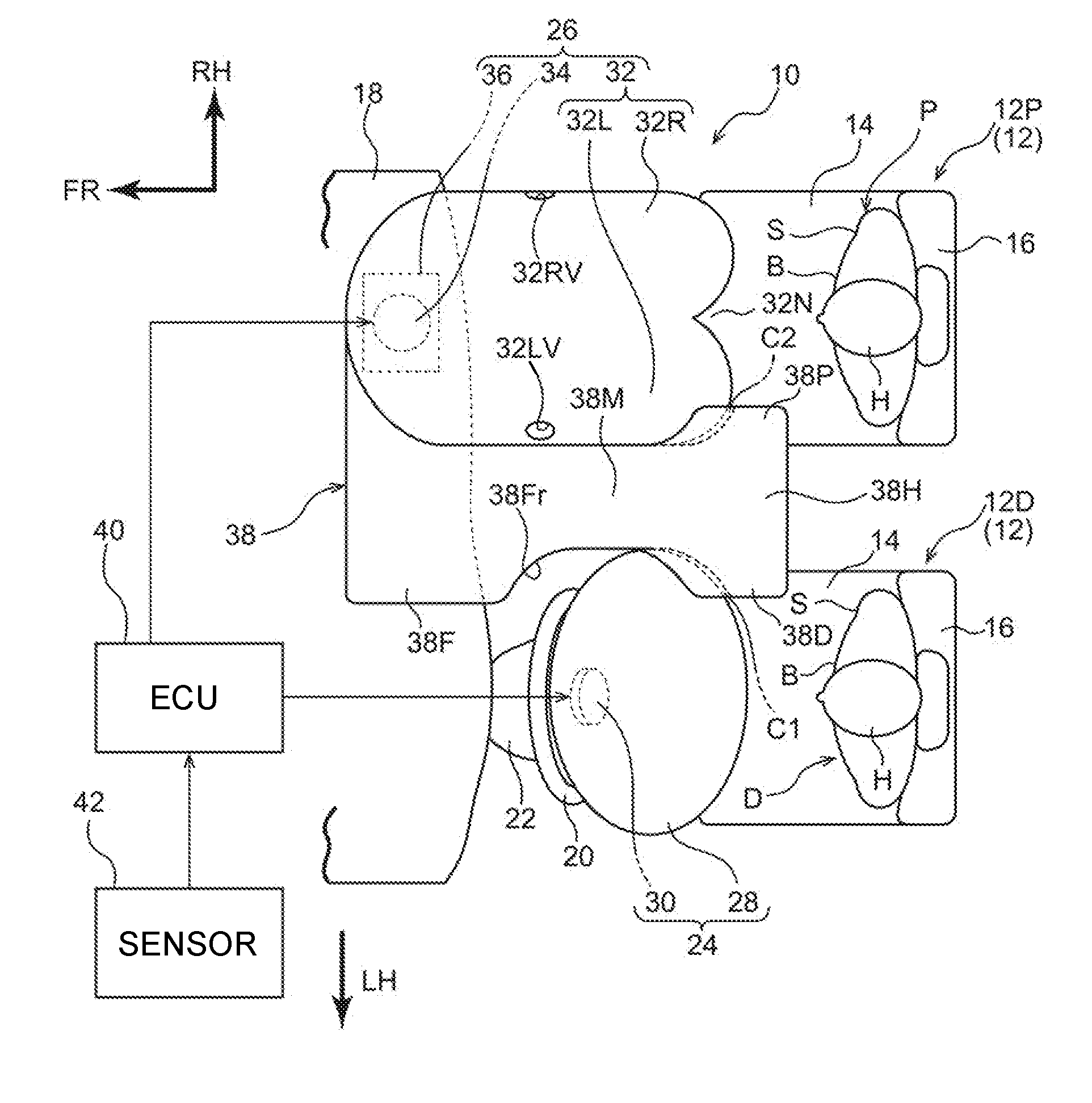
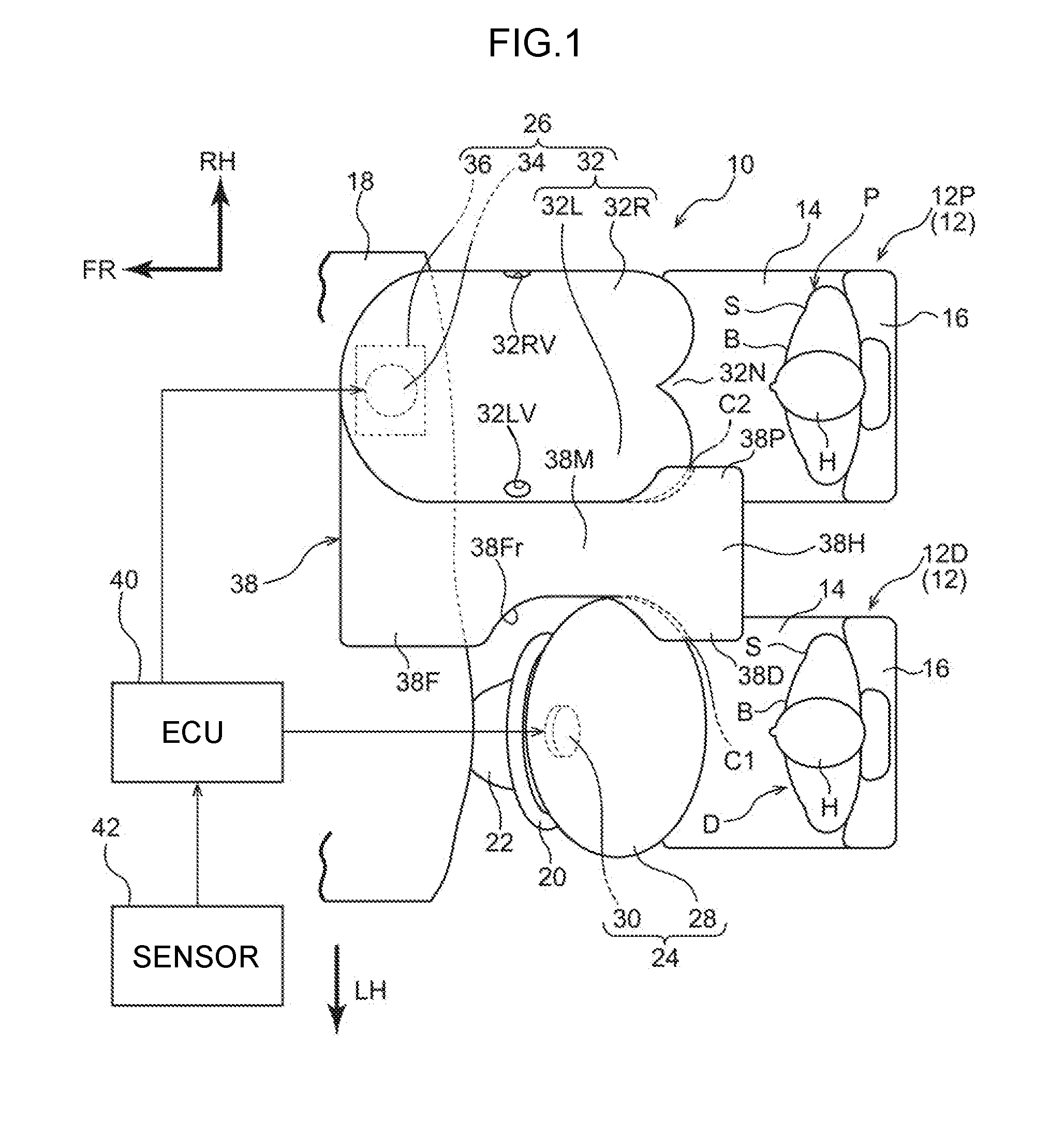
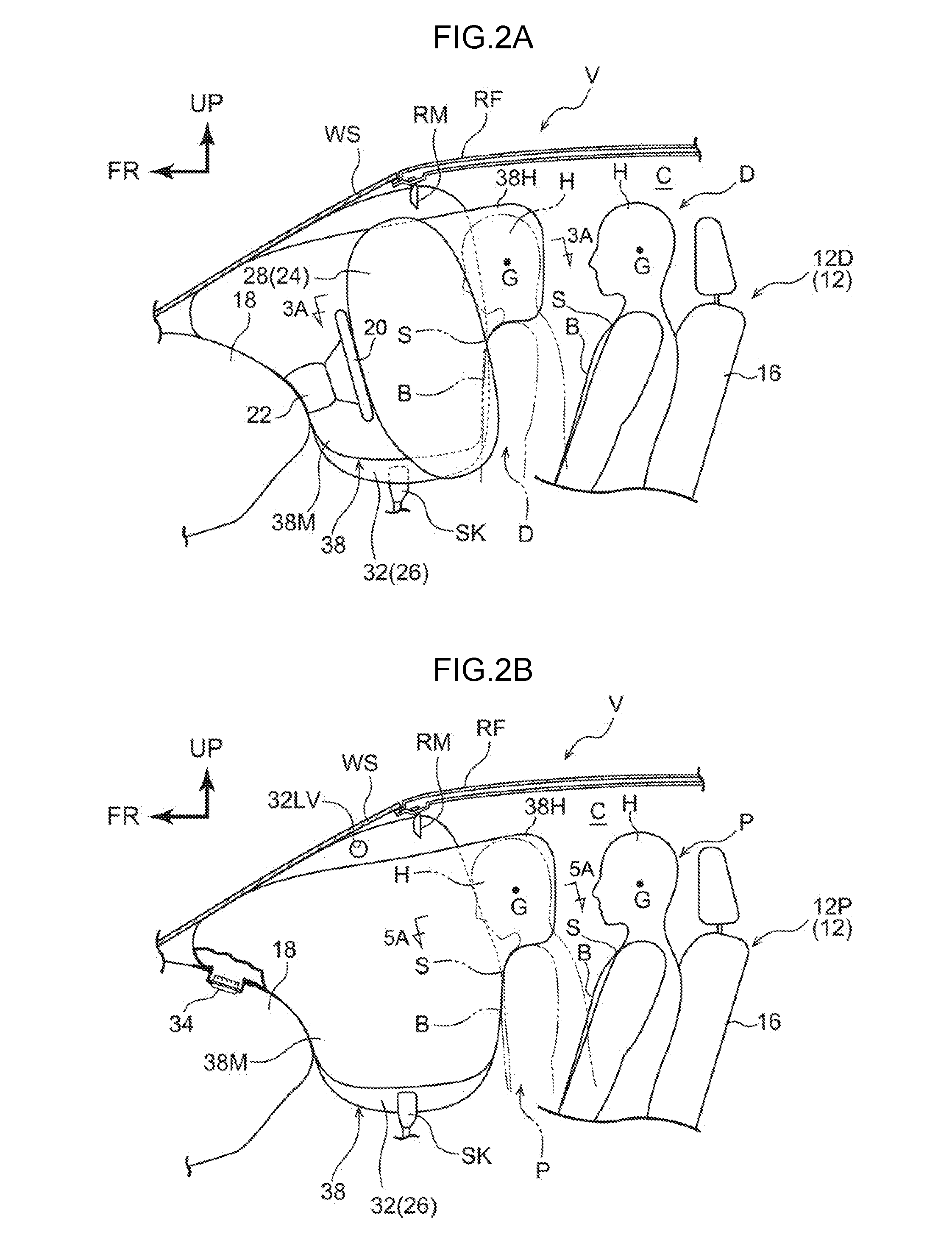
[0038]Explanation follows regarding a vehicle airbag system 10 according to an exemplary embodiment of the present invention, based on FIG. 1 to FIG. 5B. Note that in each of the drawings as appropriate, the arrow FR, the arrow UP, the arrow LH, and the arrow RH respectively indicate the front direction, upper direction, and the left side, this being one vehicle width direction side, and the right side, this being another vehicle width direction side, of an automobile V applied with the vehicle airbag system 10 (see FIGS. 2A, 2B). In the below explanation, unless specifically stated otherwise, simple reference to the front-rear, up-down, and left-right directions refers to front and rear in the vehicle front-rear direction, up and down in the vehicle up-down direction, and the left and right of the vehicle (when facing the front).

[0039]Schematic Configuration of Automobile V Interior

[0040]FIG. 1 is a plan view schematically illustrating part of the automobile V applied with the vehi...


PUM


Abstract

A vehicle airbag system including: a first airbag that is supplied with gas and inflated and deployed at a front face towards a vehicle front of a seat; and a second airbag that is supplied with gas and inflated and deployed adjacent, in a vehicle width direction, to the first airbag, and that includes an overhanging deployment section that is positioned at a vehicle rear side of the first airbag and that is inflated and deployed jutting out beside the first airbag so as to cover a vehicle width direction end portion of the first airbag from the vehicle rear.

Description

CROSS-REFERENCE TO RELATED APPLICATION[0001]This application is based on and claims priority under 35 USC 119 from Japanese Patent Application No. 2015-080215 filed on Apr. 9, 2015, the disclosure of which is incorporated by reference herein.BACKGROUND[0002]1. Technical Field[0003]The present invention relates to a vehicle airbag system.[0004]2. Related Art[0005]Devices configured with a pair of extension sections, extending toward the vehicle rear side at a height corresponding to the head or shoulders of an occupant, from locations of a pair of inflation sections are known as front passenger seat airbag devices (see, for example, Japanese Patent Application Laid-Open (JP-A) No. 2012-56371). An airbag device for a front seat for a three occupants is also known (see, for example, JPA Nos. H06-72276 and H06-24282).[0006]The configuration in JPA-No. 2012-56371 enables a front passenger seat occupant moving obliquely forward toward the collision side in an oblique collision at a driver...

Claims


Application Information

Patent Timeline
IPC IPC(8): B60R21/231
CPCB60R21/231B60R2021/23161B60R21/23138B60R2021/0009B60R2021/23107
Inventor FUKAWATASE, OSAMUNAKASHIMA, ATSUSHI
Owner TOYOTA JIDOSHA KK
Why Eureka
Try Eureka