Mechanical end-effector changer and method of using same

Active Publication Date: 2017-01-26
HIWIN TECH
View PDF0 Cites 9 Cited by
  • Summary
  • Abstract
  • Description
  • Claims
  • Application Information

AI Technical Summary

Benefits of technology

[0006]The present invention has been accomplished under the circumstances in view. It is the main object of the present invention to provide a mechanical end-ef

Problems solved by technology

This design of end-effector changer has the drawback of operational inconvenience.
Further, if the thrust bearing is lost accidentally during the operation of the robotic arm, the end-effector changer is likely to cause harm to the workers.
In this design, the connection strength between the first unit and the second unit is not strong enough

Method used


Image

  • Mechanical end-effector changer and method of using same
  • Mechanical end-effector changer and method of using same
  • Mechanical end-effector changer and method of using same

Examples


Example

[0045]Thus, this second embodiment achieves the connection between the second connection unit 50 and the first connection unit 40.

[0046]It is to be noted that, the invention further comprises a method of using a mechanical end-effector changer in a robotic arm for end-effector change.

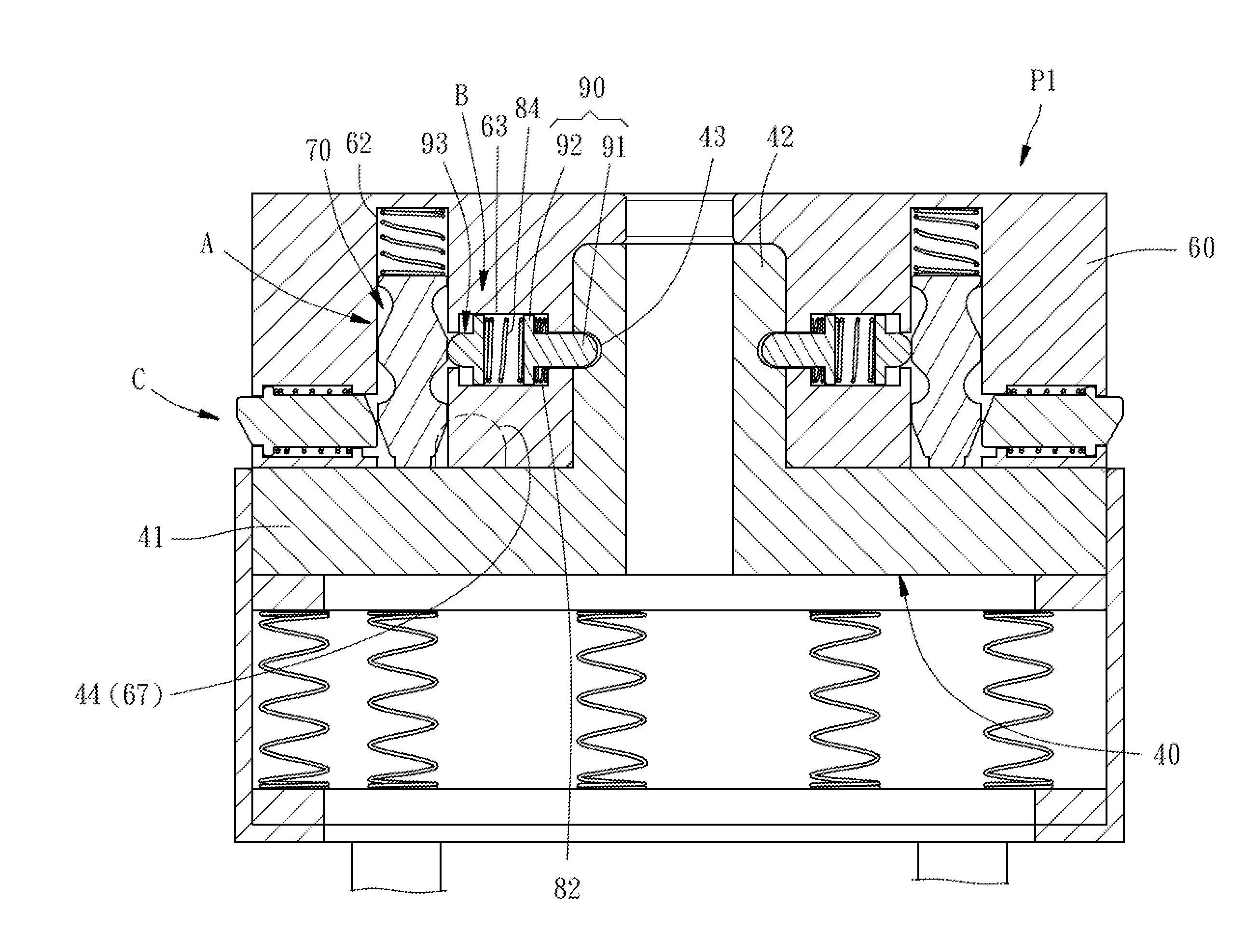
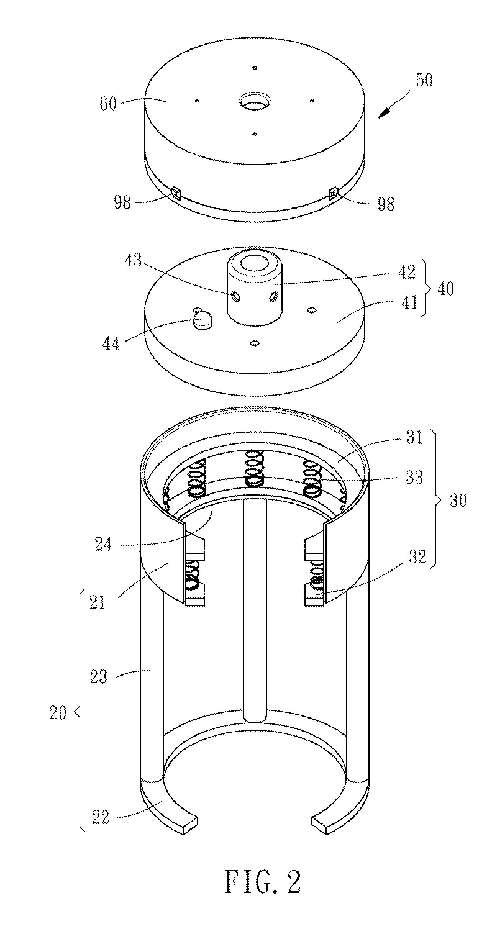
[0047]Referring also to FIGS. 5-8, the end-effector changer comprises a first connection unit 40 and a second connection unit 50. The first connection unit 40 comprises a first holder base 41 and a post 42 with an engagement hole 43. The second connection unit 50 comprises a second holder base 60, a first movable module A (for example, the aforesaid first movable member 70), a second movable module B (for example, the aforesaid second movable member 90 and third movable member 93), and a third movable module C (for example, the aforesaid fourth movable member 96). The axis of the second movable module B and the axis of the third movable module C extend perpendicular to the axis of the second holder base...


PUM


Abstract

A mechanical end-effector changer includes a first connection unit and a second connection unit. The first connection unit has mounted therein multiple movable members and mating elastic members. Subject to the linking relationship between each movable member and the respective elastic member, the first connection unit and the second connection unit can be automatically connected together or detached from each other, facilitating end-effector change.

Description

BACKGROUND OF THE INVENTION[0001]1. Field of the Invention[0002]The present invention relates to robot tool changer technology, and more particularly, to a mechanical end-effector changer at the end of a robotic arm to be changed.[0003]2. Description of the Related Art[0004]Robotic arm has been widely used for industrial manufacturing. On the one hand, it can reduce the problem of decrease in product yield caused by the implementation of repetitive workflows by labor, on the other hand, it can replace human labor in harsh environmental conditions, preventing the harmful effects on the health of workers and maintaining good machining precision. However, in the manufacturing process, robotic arm must be used with an end-effector changer for allowing the robotic arm to change end-effectors (e.g. grippers, vacuum cups or drills), for processing different workpieces.[0005]U.S. Pat. No. 6,073,512 discloses an end-effector changer entitled “Manual quick change tool changer”, which includes...

Claims


Application Information

Patent Timeline
IPC IPC(8): B23B31/171F16D1/10
CPCF16D1/10B23B31/1612B25J15/0416B23B2260/136B25J15/0408F16D1/112B23B31/10741
Inventor WONG, CHEN-MINGLIU, MING-SHIOUHUANG, YAN-SHUN
Owner HIWIN TECH
Why Eureka
Try Eureka