Method for manufacturing magnetostrictive torque sensor shaft

Pending Publication Date: 2018-07-12
PROTERIAL LTD
View PDF2 Cites 5 Cited by
  • Summary
  • Abstract
  • Description
  • Claims
  • Application Information

AI Technical Summary

Benefits of technology

[0013]According to an embodiment of the invention, a method for manufacturing a magnetostrictive torque sensor shaft can

Problems solved by technology

If a large amount of non-magnetic austenite is included in the shaft, variation in magnetic permeability when torque is applied may be small, causing a decrease in sensitivity of magnetostrictive to

Method used


Image

  • Method for manufacturing magnetostrictive torque sensor shaft
  • Method for manufacturing magnetostrictive torque sensor shaft
  • Method for manufacturing magnetostrictive torque sensor shaft

Examples


embodiment

[0023]An embodiment of the invention will be described below in conjunction with the appended drawings.

[0024]Description of Magnetostrictive Torque Sensor

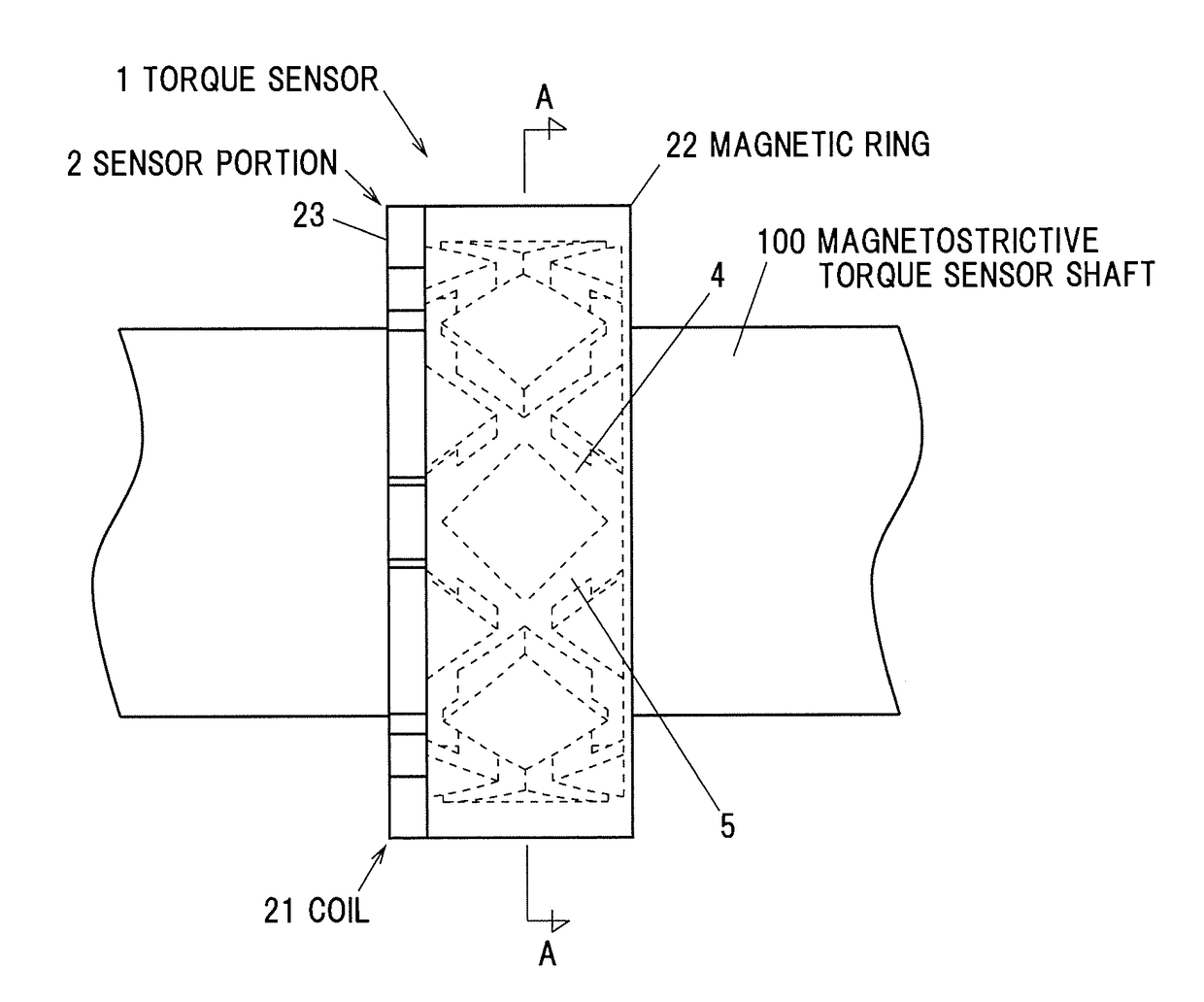
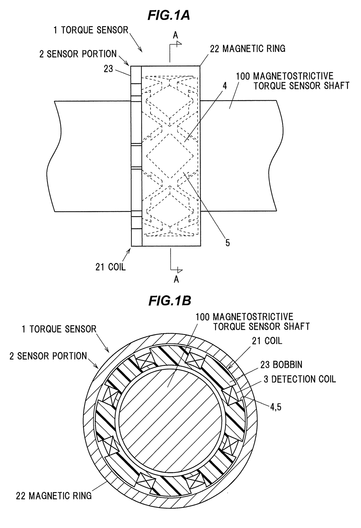
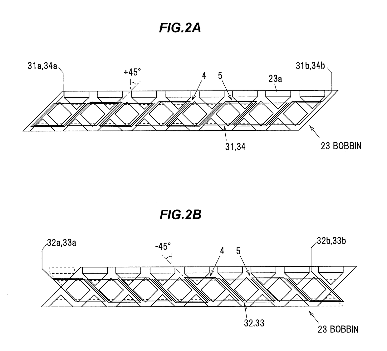
[0025]Firstly, a magnetostrictive torque sensor (hereinafter, simply referred to as “torque sensor”) will be described in reference to FIGS. 1A to 3. FIGS. 1A and 1B are diagrams illustrating an example of a sensor portion of a torque sensor, wherein FIG. 1A is a side view when attached to a shaft and FIG. 1B is a cross sectional view taken on line A-A of FIG. 1A. FIGS. 2A and 2B are schematic exploded plan views showing a bobbin, wherein FIG. 2A is an explanatory diagram illustrating first and fourth detection coils and FIG. 2B is an explanatory diagram illustrating second and third detection coils. FIG. 3 is a circuit diagram illustrating an example of a measurement portion which measures torque applied to the shaft based on a detection signal of the torque sensor.

[0026]As shown in FIGS. 1A and 1B, a sensor portion 2 of a torque ...


PUM

PropertyMeasurementUnit
Pressureaaaaaaaaaa
Pressureaaaaaaaaaa
Lengthaaaaaaaaaa

Abstract

Provided is a method for manufacturing a magnetostrictive torque sensor shaft mounting a sensor portion of a magnetostrictive torque sensor. The method includes conducting heat treatment on a shaft material including chrome steel or chrome-molybdenum steel by carburizing, quenching and tempering, and conducting shot peening on the shaft material after the heat treatment at least on a position where the sensor portion is to be mounted. The shot peening is conducted by firing shot with a particle size of not less than 0.6 mm and a Rockwell hardness of not less than 60 at a jet pressure of not less than 0.4 MPa for a jet exposure time of not less than 2 minutes.

Description

[0001]The present application is based on Japanese patent application No.2017-002547 filed on Jan. 11, 2017, the entire contents of which are incorporated herein by reference.BACKGROUND OF THE INVENTION1. FIELD OF THE INVENTION[0002]The invention relates to a method for manufacturing a magnetostrictive torque sensor shaft.2. DESCRIPTION OF THE RELATED ART[0003]Magnetostrictive torque sensors known are used on a magnetostrictive shaft with magnetic permeability varying according to applied stress, and are configured such that variation in magnetic permeability of the shaft when distorted under the applied torque is detected as variation in inductance of a detection coil, thereby detecting torque applied to the shaft (see, e.g., JP 2002 / 340701 A).SUMMARY OF THE INVENTION[0004]A known steel material used for the magnetostrictive shaft includes a non-magnetic microstructure called austenite. The austenite is a solid solution of 7-iron having a face-centered cubic lattice structure with ...

Claims


Application Information

Patent Timeline
IPC IPC(8): C21D9/00G01L3/10B24C1/10C21D8/06C21D8/12C21D7/06C21D6/00
CPCC21D8/1255C21D8/1216C21D7/06C21D8/1277C21D6/004G01L3/103B24C1/10C21D8/065C21D9/0075G01L3/10C21D9/28B24C3/322B24C11/00H10N35/01
Inventor NAKAMURA, TERUYUKI
Owner PROTERIAL LTD
Why Eureka
Try Eureka