

Retractable table
- Summary
- Abstract
- Description
- Claims
- Application Information
AI Technical Summary
Benefits of technology
Problems solved by technology
Method used
Image

Examples
Embodiment Construction
[0040]In order that the invention may be more clearly understood an embodiment thereof will now be described, by way of example only, with reference to the accompanying drawings, of which:
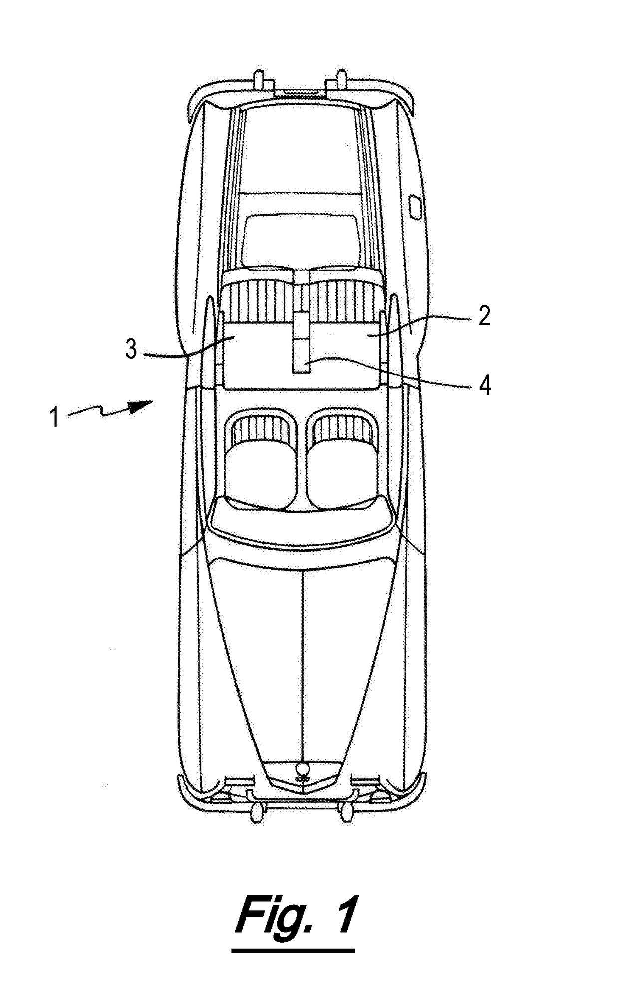
[0041]FIG. 1 shows a plan view of an automobile comprising the retractable table assembly of the invention in the stowed position;
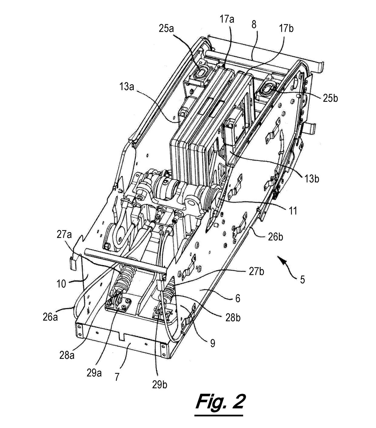
[0042]FIG. 2 shows an isometric view of the retractable table assembly of FIG. 1 with both tabletops in the stowed position;
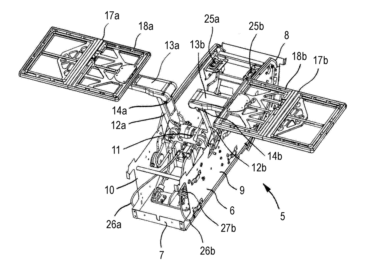
[0043]FIG. 3 shows an isometric view of the retractable table assembly of FIGS. 1 and 2 with both tabletops in the laterally deployed position;
[0044]FIG. 4 shows a side view of one of the tabletops in the retractable table assembly of FIGS. 1-3 and its associated deployment mechanism, in the stowed state.
[0045]FIG. 5 shows a side view of the tabletop and deployment mechanism of FIG. 4 with the arm in the deployed state;
[0046]FIG. 6 shows a rear perspective view of the retractable table assembly of FIGS. 1-3 with one tabletop in a centrally deployed ...
PUM
 Abstract
Description
Claims
Application Information