Descender

a technology of escalators and descenders, which is applied in the direction of life-saving devices, safety belts, hoisting equipment, etc., can solve the problems of difficult locking of the descender to stop the descent, and the speed at which the rope is able to travel through the descender is limited,

Inactive Publication Date: 2018-10-25
CHECKMATE ELEVATORING & SAFETY
View PDF0 Cites 2 Cited by
  • Summary
  • Abstract
  • Description
  • Claims
  • Application Information

AI Technical Summary

Benefits of technology

The patent text describes a device with a port that can direct a rope towards a specific wall. This makes it easier to control the rope's movement. The device also has a groove that makes it easy to wrap the rope around the housing. The technical effect of this invention is to make it easier to control the movement of rope in a device.

Problems solved by technology

The technical problem addressed in this patent text is the difficulty of locking known descent devices, such as constant rate descenders, to halt the descent. The invention aims to provide an improved descender device and method of using it with a rope.

Method used


Image

  • Descender
  • Descender
  • Descender

Examples


Embodiment Construction

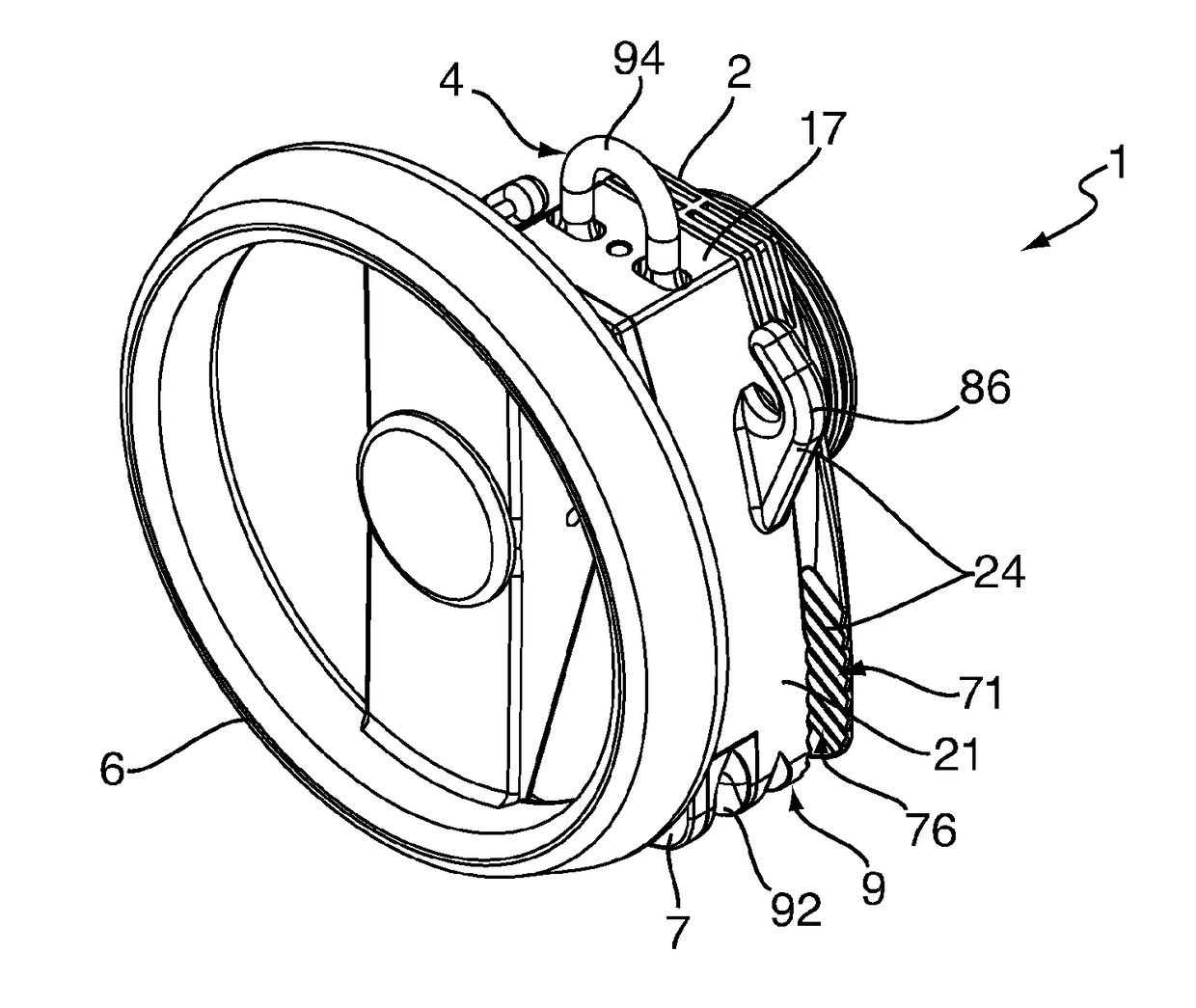
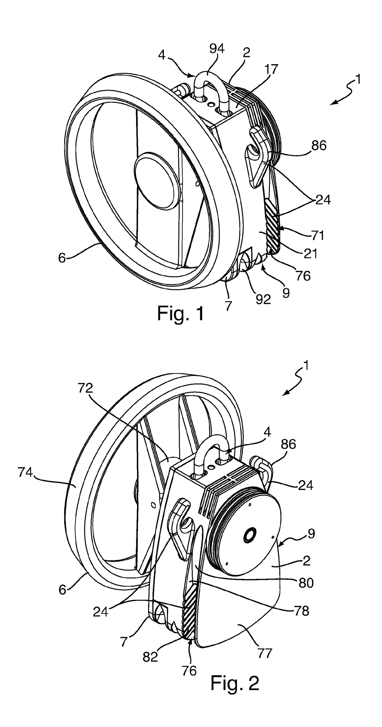
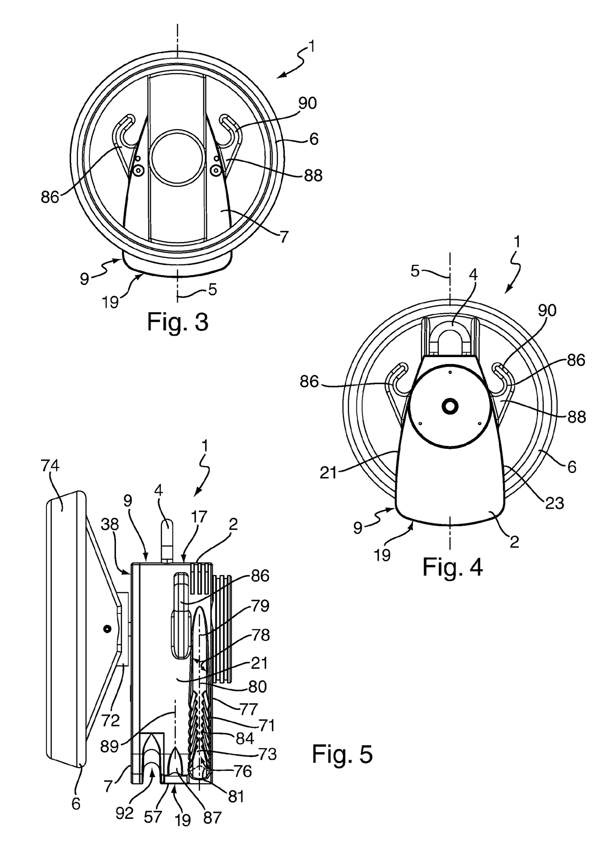
[0058]FIGS. 1 to 5 show external views of a descender 1 according to a preferred embodiment of the present invention. The device comprises a main body 2 having an attachment means 4 for connection to an anchor point or person and a wheel 6 that may be gripped and turned by a user of the descender 1.

[0059]The main body 2 has a hollow interior 3 that is closed by front face plate 7 that is removably attached to the main body. The main body 2 and front face plate 7, together with other parts to be described below, form a housing 9 for components held within the housing.

[0060]The main body 2 is a monobloc, that is, a unitary body formed as a single piece. In this example, the main body is formed as a cast aluminium body and the front face plate is an aluminium plate. Preferably, these components have anodised external surfaces. The cast monobloc will be machined where necessary.

[0061]As shown in FIG. 6, within the housing 9 there is mounted a drive pulley 8 with a circumferential groove...


PUM


Abstract

A descender device for manually raising and lowering an object or person on a rope has a housing (which has opposing first and second ends and opposing side walls), an attachment means (provided at the first end of the housing and configured for attachment to an anchor point or to the object or person to be raised or lowered), rope entry and exit ports (at the second end of the housing), a drive pulley (around which the rope may be engaged), a centrifugal brake (configured to limit the speed of rotation of the drive pulley), a gear assembly, a wheel (arranged to be gripped by a user of the device), and a rope retaining means provided on an outside of the housing. The wheel is connected to the gear assembly. The rope retaining means comprises a projection and at least one groove.

Description


Claims


Application Information

Patent Timeline
Owner CHECKMATE ELEVATORING & SAFETY
Why Eureka
Try Eureka