

Folding barn style door and hardware
a barn style and hardware technology, applied in the field of sliding doors, can solve the problems that the roller and the attachment do not permit the use of solid door panels, and achieve the effect of simple installation
- Summary
- Abstract
- Description
- Claims
- Application Information
AI Technical Summary
Benefits of technology
Problems solved by technology
Method used
Image

Examples
Embodiment Construction
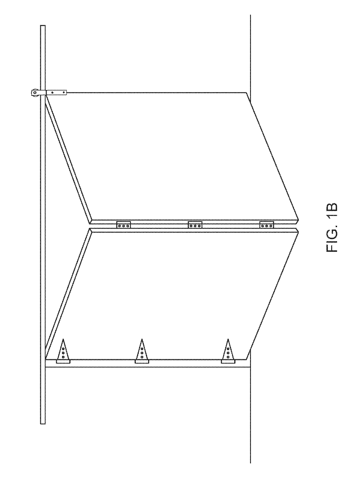
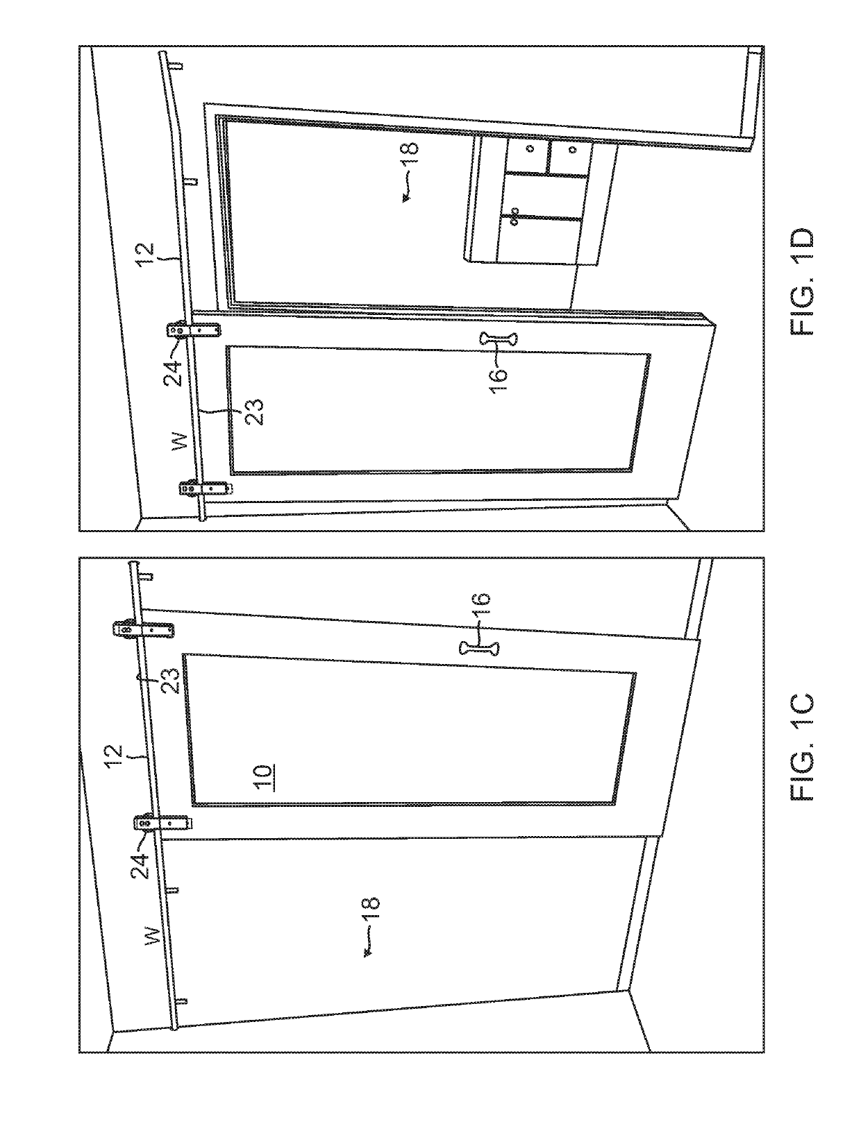
[0027]Referring to FIGS. 2A-2D, door panels 20 are shown hinged together along their vertical sides 17 so as to be foldable. Each door panel 20 has a width one half or more of the opening to be covered. FIG. 2A shows a fully closed position while FIG. 1D shows a fully open position. FIGS. 2B and 2C show the door panels 20 in intermediate positions.
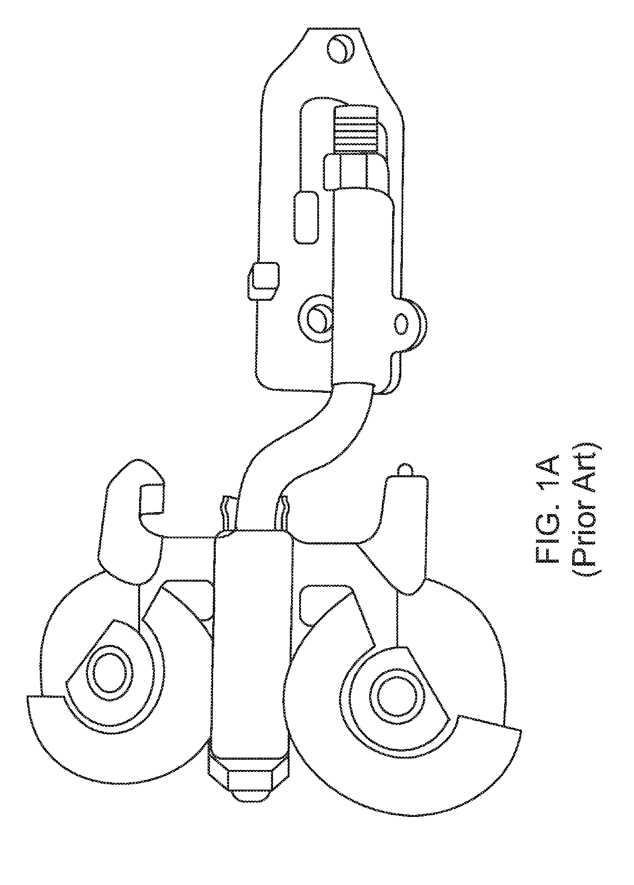
[0028]Each of the door panels 20 has a U-shaped roller assembly 22 pivotally attached to the top edge 23 of each door panel 20. The construction and preferred dimensions of the rotating exposed roller assembly 22 is shown in FIGS. 5 and 6. The door panels 20 can be pushed to be completely on the side of the opening by having the track 12 extending to the side of the opening.
[0029]The rotating exposed roller assembly 22 consists of a standard U-shaped roller 24 having two opposing round members 26 with an internal taper 28 in between, a pivotable pin 30 connected to the center of the U-shaped roller assembly 22 that permits the U-shaped rol...
PUM
 Abstract
Description
Claims
Application Information