Image reader

a technology of image reader and contact lever, which is applied in the field of image reader, can solve the problems of increasing the force required for the leading end of the document to push up the contact lever, affecting the balance of the document, and not being able to appropriately maintain the posture of the contact lever

Active Publication Date: 2019-10-31
SEIKO EPSON CORP
View PDF0 Cites 4 Cited by
  • Summary
  • Abstract
  • Description
  • Claims
  • Application Information

AI Technical Summary

Benefits of technology

[0010]An advantage of some aspects of the disclosure is to obtain a high possibility that it is possible to maintain an appropriate posture of the contact lever for a longer time in an image reader that employs a contact detecting unit that comes into contact with the document so as to detect passing of the document.
[0012]In this configuration, the first posture is one of the postures of the reader and means a posture in which the document transport path is extended along the horizontal direction, a posture that can be taken for a longest time of a service life of the reader, and a normal installation posture. The image reader according to the disclosure uses such features described above. In other words, the rotation-contact member, with which the leading end of the document comes into contact such that the rotation-contact member rotates, is positioned on the upper side of the document transport path, the contact portion projects from the upper side toward the lower side of the document transport path, and the center-of-gravity position of the rotation-contact member is on the lower side from the rotation center in the first posture. Therefore, the rotation-contact member can be lowered by its own weight without a need of the pressing force of the pressing unit and block the document transport path.
[0013]Therefore, in the first posture, that is, the posture that is highly likely to be taken for the longest time of the service life of the reader, it is possible to appropriately maintain the posture of the rotation-contact member in which the pressing force of the pressing unit does not act against a force by which the rotation-contact member retracts from the document transport path due to action of gravity. In addition, an unnecessary opposite force does not act on the pressing unit in the first posture, and thus it is possible to appropriately maintain the pressing force of the pressing unit over a long period.
[0021]In this configuration, the contact portions are provided at appropriate intervals along the document width direction. Therefore, it is possible to reduce the weight of the rotation-contact member, and it is possible to push up the rotation-contact member with a light force.
[0023]In this configuration, the image reader includes the sensor unit that reads the document, and the sensor unit holds the document in cooperation with the transport roller. Therefore, there is no need to provide a roller that is paired with the transport roller, and thus it is possible to achieve a reduction in cost of the reader.
[0025]In this configuration, the image reader includes the control unit that receives the detection signal from the detecting unit and controls the transport roller, and the control unit starts the driving of the transport roller and the reading of the document after a predetermined time after the control unit detects that the leading end of the document rotates the rotation-contact member, based on the detection signal. Therefore, it is possible to avoid missing a part of an image of the leading end of the document.

Problems solved by technology

However, when the sensor is used in a reader like the scanner disclosed in JP-A-2014-012594, which is small and used by being placed on a desk or being carried outside, the following specific technical problems arise.
When a state continues for a long period, in which the contact lever moves against a force that causes the contact lever to retract from the document transport path due to the action of gravity, and a spring causes the contact lever to project to the document transport path, there is a concern that, as time passes, a balance will be lost between a force by which the contact lever retracts from the document transport path due to the action of gravity and a force by which the spring causes the contact lever to project to the document transport path, and thus it is not possible to appropriately maintain the posture of the contact lever.
In addition, when the spring force of the spring increases, there is a concern that a force necessary for the leading end of the document to push up the contact lever will increase, thus, it is not possible for the leading end of the document having the low stiffness to push up the contact lever, and jam will occur.
When the spring force of the spring is set to the minimum necessary degree in order to avoid such a problem, a very delicate balance is kept between the force by which the contact lever retracts from the document transport path due to the action of gravity and the force by which the spring causes the contact lever to project to the document transport path, and thus the problem described above arises still more easily.
In addition, an unnecessary opposite force does not act on the pressing unit in the first posture, and thus it is possible to appropriately maintain the pressing force of the pressing unit over a long period.

Method used


Image

  • Image reader
  • Image reader
  • Image reader

Examples


Embodiment Construction

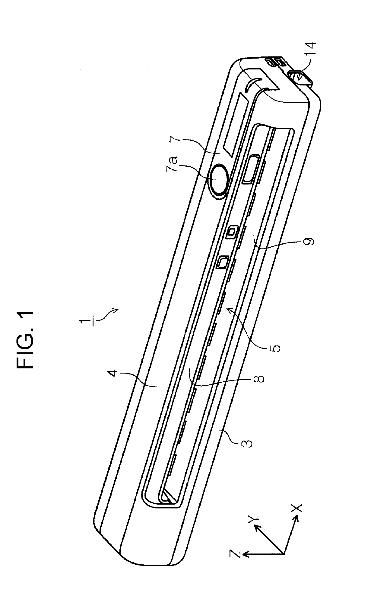
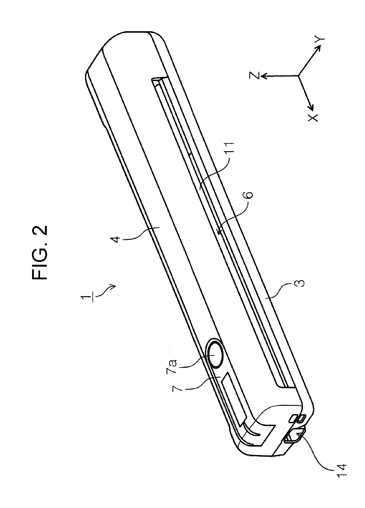
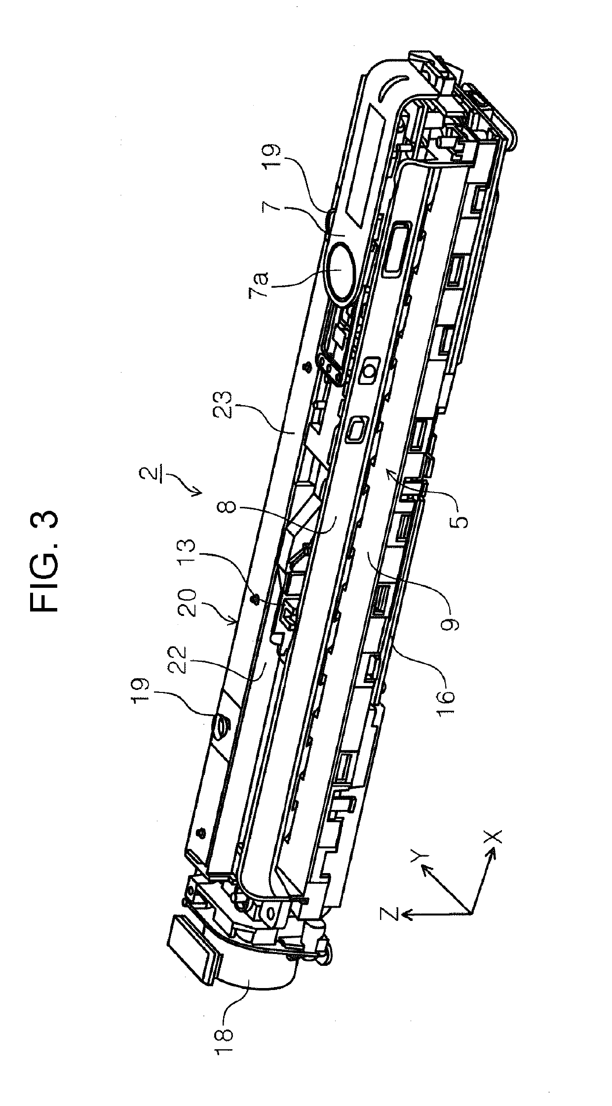
[0045]Hereinafter, embodiments of an image reader according to the present disclosure will be described with reference to the drawings. In this embodiment, an example of the image reader includes a handy scanner that is configured to read one of a front surface and a back surface of the document.

[0046]In the drawings, an X direction in an X-Y-Z coordinate system is an apparatus width direction or the document width direction that is a direction intersecting the document transport direction. In addition, a Y direction is the document transport direction. A Z direction is a perpendicular direction and an apparatus height direction. In addition, a +Y direction side is set as the document discharge direction, a right side and a left side are set as a +X direction and −X direction, respectively, when the document insertion opening 5 is in front.

[0047]In addition, a +Z direction is set as a vertically upward direction, and a −Z direction side is set as a vertically downward direction. In ...


PUM


Abstract

An image reader includes: a document transport path that is extended along a horizontal direction when the reader has a first posture and that transports the document; a transport roller that transports the document in the document transport path; a rotation-contact member document path rotating to have a posture in which a contact portion that comes into contact with the document blocks the document transport path and a posture in which the contact portion opens the document transport path; path A rotation center of the rotation-contact member is positioned on an upper side of the document transport path in the first posture and the contact portion projects from the upper side toward a lower side of the document transport path. A center-of-gravity position of the rotation-contact member is on a lower side from the rotation center in the first posture.

Description

[0001]The present application is based on, and claims priority from JP Application Serial Number 2018-087157, filed Apr. 27, 2018, the disclosure of which is hereby incorporated by reference herein in its entirety.BACKGROUND1. Technical Field[0002]The present disclosure relates to an image reader that reads the document.2. Related Art[0003]JP-A-2014-012594 discloses a document scanner as an example of an image reader. The document scanner is small and used by being placed on a desk or being carried outside.[0004]A sensor, which detects that the document is inserted, is provided in an document transport path through which the document is transported. In JP-A-2014-012594, an entry sensor 113 corresponds to the sensor. In addition, JP-A-2014-012594 provides the description that the entry sensor 113 may be any sensor such as a reflective optical sensor, a transmissive optical sensor, or a lever-type contact sensor.[0005]From a viewpoint of suppressing costs of a reader or from a viewpoi...

Claims


Application Information

Patent Timeline
Patent Type & Authority Applications(United States)
IPC IPC(8): H04N1/00
CPCH04N1/00588H04N1/00594H04N1/00816H04N1/00737H04N1/00663
Inventor KIKUCHI, KOICHINAGAI, YOSHIKAZU
Owner SEIKO EPSON CORP
Why Eureka
Try Eureka