Display device

a display device and display technology, applied in the direction of display/control unit casings, electrical apparatus casings/cabinets/drawers, identification means, etc., can solve the problems of complicated overall structure and difficult to break the connection line, and achieve the effect of reliably reducing the stress applied to the display and easy installation

Active Publication Date: 2021-11-25
SHARP KK
View PDF0 Cites 2 Cited by
  • Summary
  • Abstract
  • Description
  • Claims
  • Application Information

AI Technical Summary

Benefits of technology

[0020]According to the above-described aspect of the present invention, unlike the winding type display device, a drive circuit portion does not need rotation or movement action, so that a display device easy to install and unlikely to cause a failure may be provided.
[0021]In addition, according to the above-described aspect of the present invention, since the display screen can be prevented from being overlapped and wound, it is possible to provide a display device able to reliably reduce stress applied to the display.

Problems solved by technology

In a flexible display device disclosed in PTL 3, part of the connecting line from the connecting section is always wound around the first reel, whereby force received by the connecting section is dispersed, and thus the connecting line is difficult to be broken.
This causes the overall structure to be complicated.

Method used


Image

  • Display device
  • Display device
  • Display device

Examples


first embodiment

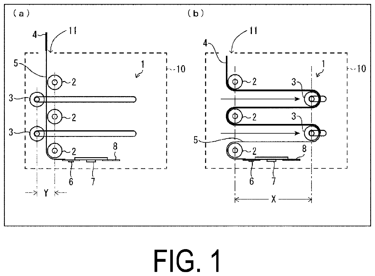
[0028]First, it is described below how the flexible display panel 1 (display area for display) is housed in the accommodation section 10 in a housing and pull-out type display device.

[0029](a) of FIG. 1 is an explanatory diagram illustrating a state in which the flexible display panel 1 is pulled out from the accommodation section 10 (the time of pull-out, that is, a case of displaying an image on the flexible display panel). (b) of FIG. 1 is an explanatory diagram illustrating a case in which the flexible display panel 1 is housed (the time of housing). (c) of FIG. 1 is an explanatory diagram in which a state of the accommodation section 10 is three-dimensionally depicted when the flexible display panel 1 is housed in (b) of FIG. 1.

[0030]As illustrated in (a) to (c) of FIG. 1, the display device includes the flexible display panel 1 and the accommodation section 10. The display device includes a plurality of fixed guide members 2 formed of, for example, rollers and the like unable ...

second embodiment

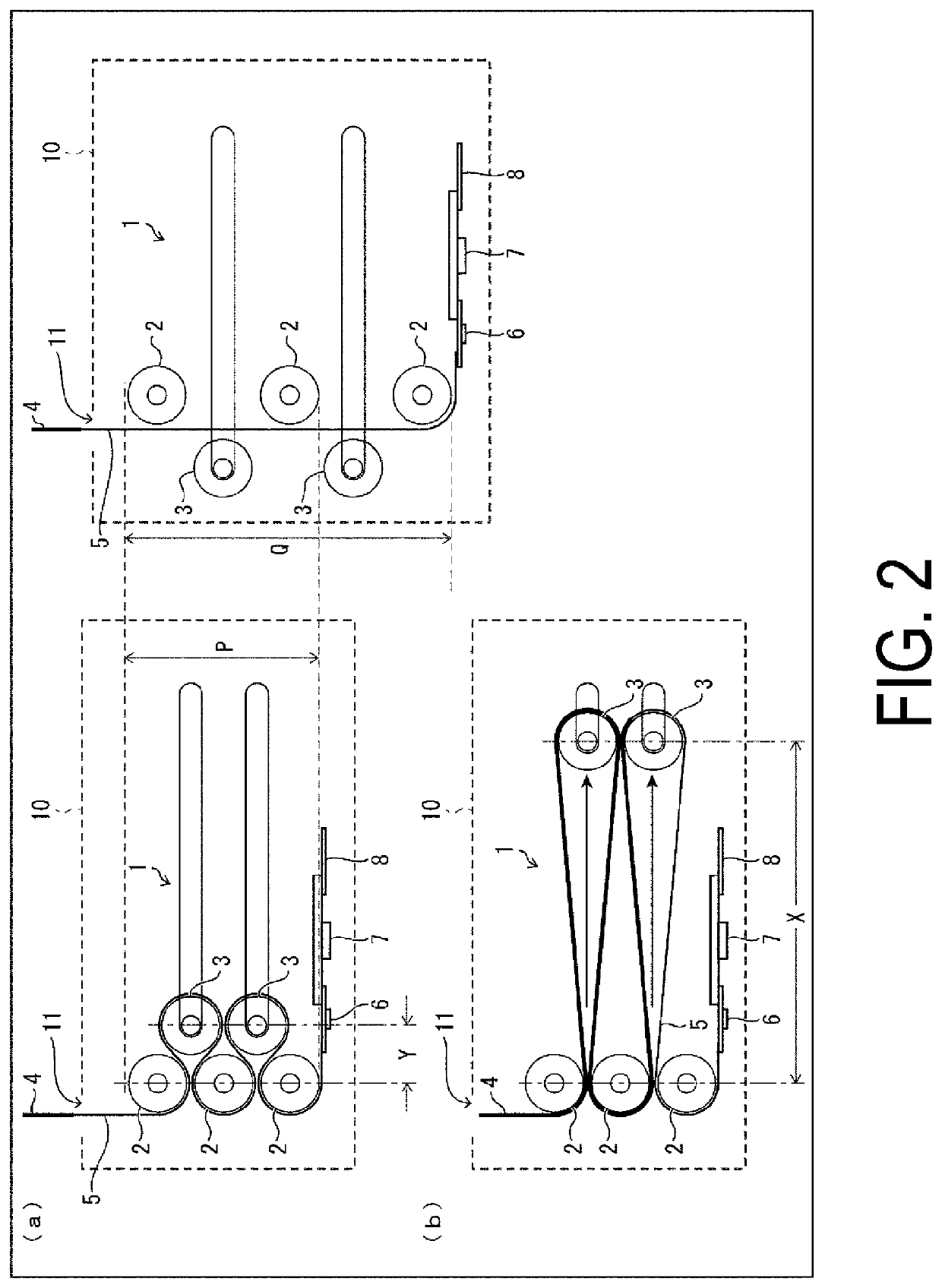
[0051]A second embodiment of the present invention will be described below with reference to FIG. 2. Note that for the sake of convenience in description, members having the same functions as the members described in the first embodiment will be given the same reference signs, and descriptions thereof will be omitted.

[0052]In a housing and pull-out type display device of the second embodiment, a configuration to pull out a flexible display panel 1 is different from that of the first embodiment.

[0053]The configuration of the second embodiment differs from the configuration of the first embodiment in a point that fixed guide members 2 and movable guide members 3 are disposed in the positions and at the intervals illustrated in FIG. 2. This point will be described below.

[0054]That is, according to the configuration of the first embodiment, each of the plurality of movable guide members 3 passes through between the corresponding two fixed guide members 2 and moves in a predetermined dir...

third embodiment

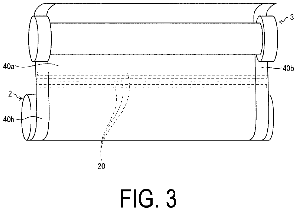
[0061]A third embodiment of the present invention will be described below with reference to FIG. 3. For the sake of convenience in description, members having the same functions as the members described in the first and second embodiments will be given the same reference signs, and descriptions thereof will be omitted.

[0062]The fixed guide member 2 is configured to be disposed in such a manner as to make contact with a rear face of the flexible display panel 1. This contact does not cause the rear face of the flexible display panel 1 to experience stress, scratches, or the like.

[0063]On the other hand, in the movable guide member 3, a display surface of the flexible display panel 1 is disposed to be in contact with the fixed guide member 2. When disposed in this manner, the display surface of the flexible display panel 1 is damaged, and the display of the flexible display panel 1 is adversely affected.

[0064]To deal with this, the third embodiment further includes the following confi...


PUM


Abstract

A display device includes a flexible display panel, and an accommodation section configured to house the flexible display panel and provided with at least one movable guide member being movable and a plurality of fixed guide members configured to support the flexible display panel, where a distance between the at least one movable guide member and the plurality of fixed guide members at a time of pull-out is different from that at a time of housing.

Description

TECHNICAL FIELD[0001]The present invention relates to a display device configured to pull out or house a flexible display panel.BACKGROUND ART[0002]An electronic device disclosed in Patent Literature (PTL) 1 includes a first housing, a second housing, a flexible display, and a drive unit. The first housing has a first face where a keyboard is provided. The second housing has a second face that is foldably connected with the first housing, comes close to the first face in a folded state, and is spaced apart from the first face in an unfolded state.[0003]The flexible display has a display surface on which an image is displayed, is housed in an accommodation section provided in the first housing in such a manner as to be able to exit therefrom and enter therein, covers the second face at least partially in a state in which at least part thereof exits from the accommodation section, and is supported by the first housing and the second housing. The drive unit moves when the first housing...

Claims


Application Information

Patent Timeline
Patent Type & Authority Applications(United States)
IPC IPC(8): H05K5/02H05K5/00
CPCH05K5/0217H05K5/0017G09F9/00G09F9/30G06F1/1652
Inventor SUGA, KATSUYUKIYASUDA, YUKI
Owner SHARP KK
Why Eureka
Try Eureka