Battery charger device

a battery charger and battery pack technology, applied in the direction of electrochemical generators, cell components, cell component details, etc., can solve the problem that the battery pack cannot be held stably, and achieve the effect of more stab holding

Inactive Publication Date: 2000-09-26
PANASONIC CORP
View PDF4 Cites 190 Cited by
  • Summary
  • Abstract
  • Description
  • Claims
  • Application Information

AI Technical Summary

Benefits of technology

According to this configuration, even when a load is applied in a holding state to the lever in the direction toward the back face of the pocket, a component force in the rotation direction

Problems solved by technology

However, the battery charger device of the prior art has a problem in that, when a large battery pa

Method used


Image

  • Battery charger device
  • Battery charger device
  • Battery charger device

Examples


first embodiment

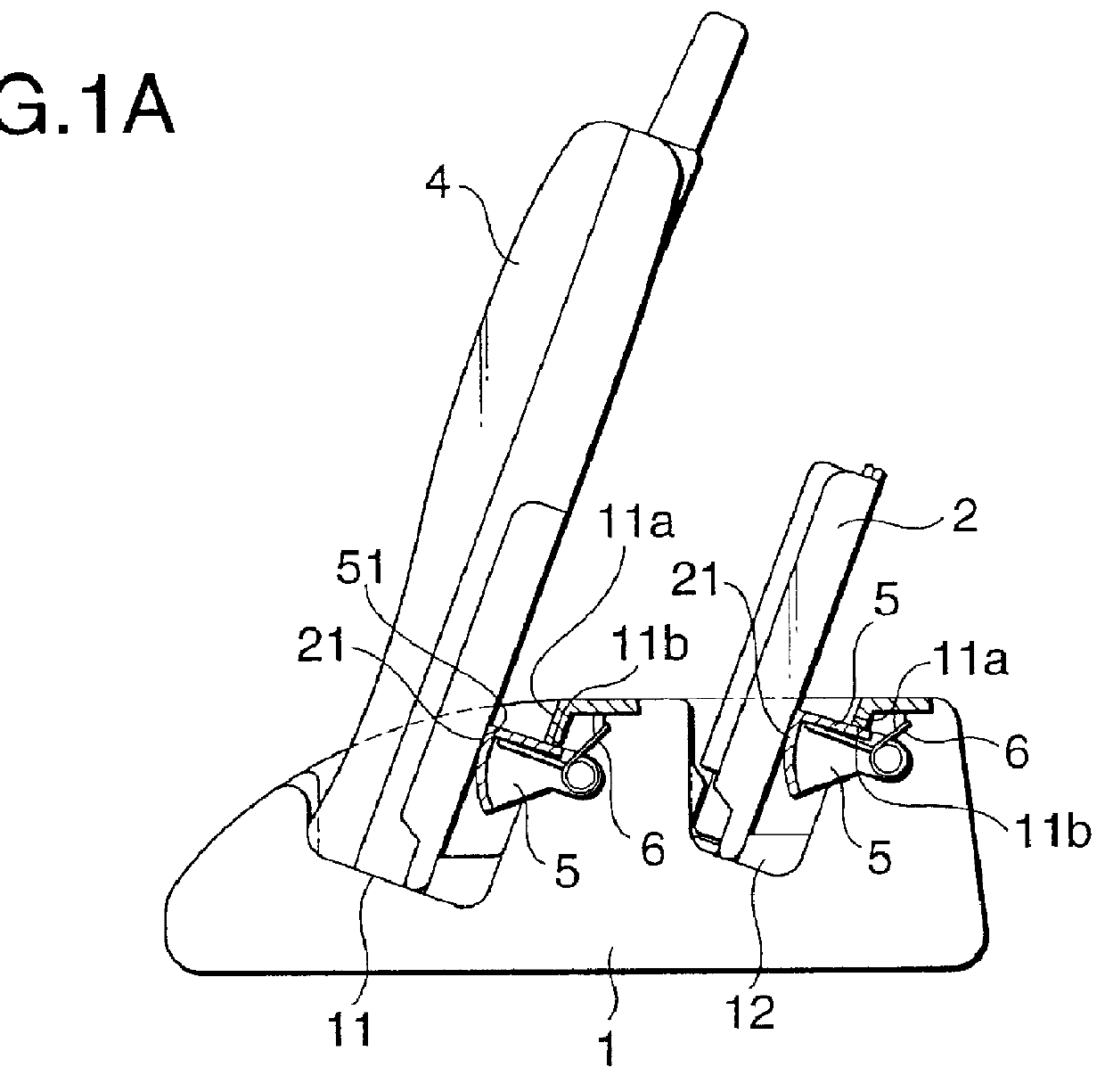
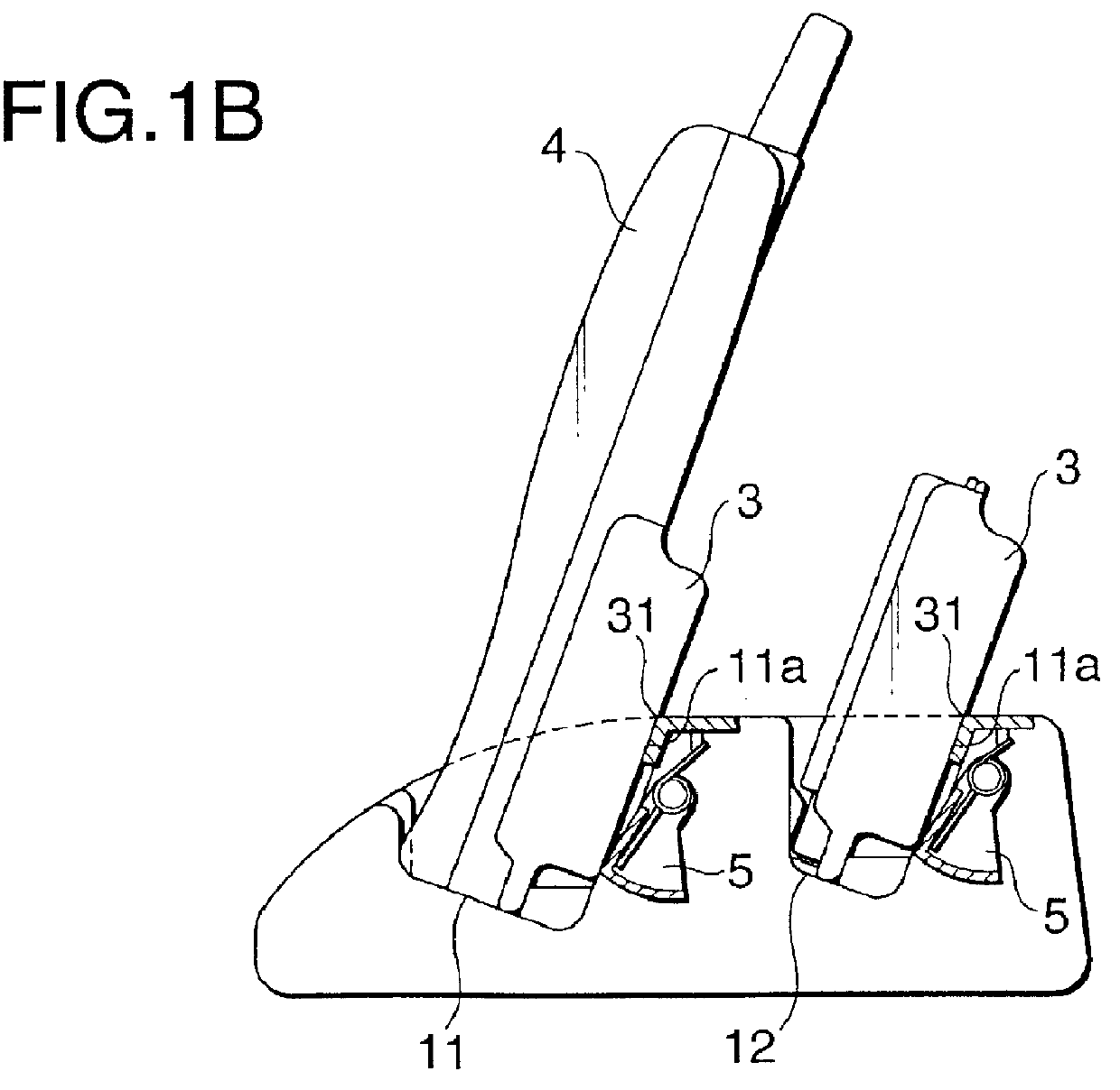
A first embodiment of the invention is a battery charger device in which a rotatable front-pocket lever is disposed in a back face of a front pocket for holding a portable telephone, and a rotatable rear-pocket lever is disposed in a back face of a rear pocket for holding a battery pack.

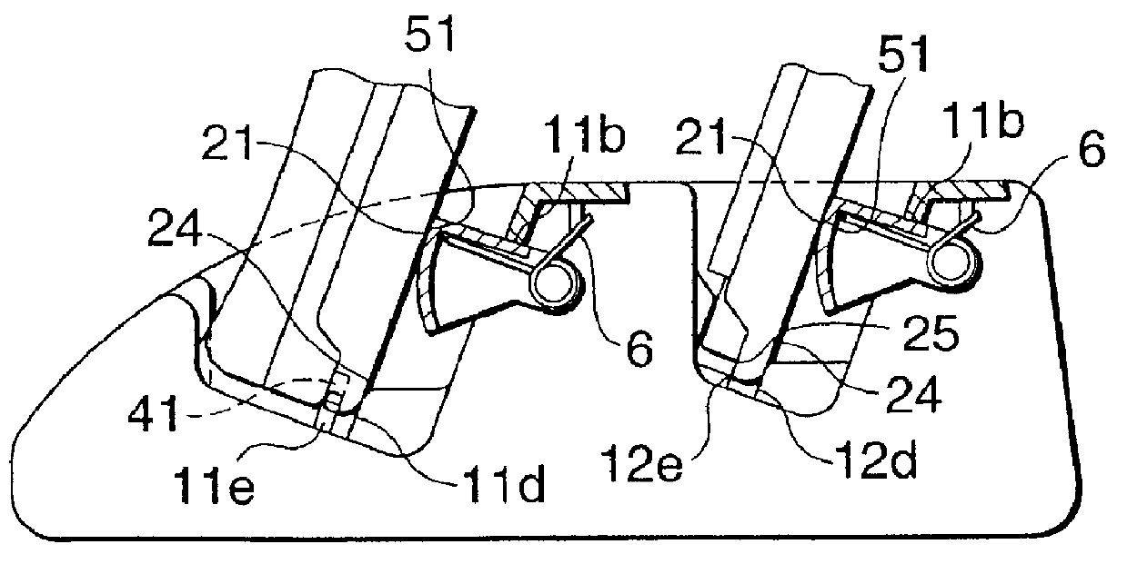
FIGS. 1A and 1B are views showing the configuration of the battery charger device of the first embodiment of the invention. Referring to FIGS. 1A and 1B, the battery charger device 1 is a battery charger comprising: a front pocket 11 applicable to a portable telephone 4 having a large battery pack 3; and a rear pocket 12 applicable to a large battery pack 3. Each of levers 5 is a lever which is urged by a spiral spring 6 that is disposed inside the lever. Each lever is placed in the back face 11a of the corresponding pocket, and fixed to a predetermined position by a stopper 11b. Each of small-battery receiving faces 21 is a face which receives a small battery pack that is held by the corresponding l...

second embodiment

A second embodiment of the invention is a battery charger device in which a small battery pack is guided to a proper holding position by the upper face of a block that is disposed in a lower portion of the back face of a pocket, the front face of the block having a relatively large area is caused to abut against the common back face to assist the small battery pack in self-standing, and a portable telephone or the like is held in a proper position by a lever having a spiral spring of an urging force of a degree that enables the lever not to stop midway.

FIGS. 2A to 2C are views showing the configuration of the battery charger device of the second embodiment of the invention. Referring to FIG. 2A, a bottom face 22 and a back face 23 are the bottom face and the back face of the small battery pack 2, respectively. In the case where the portable telephone 4 having the small battery pack 2, and the small battery pack 2 are to be inserted into the front and rear pockets 11 and 12, respecti...

third embodiment

A third embodiment of the invention is a battery charger device in which a jaw portion is disposed on a front face of a front pocket, and the height of the pocket front face corresponds to the position of the lever.

FIGS. 3A to 3C are views showing the configuration of the battery charger device of the third embodiment of the invention. Referring to FIG. 3A, a wall face 32 is a wall faces which is formed on a large battery pack 3 and which serves as a discrimination point with respect to a small battery pack 2. A lever tip end 52 is the highest point of each lever 5 in a natural state, and is to abut against the wall face 32. A jaw 11f is a jaw portion which is disposed on the front face of the front pocket 11 (FIG. 3C), and increases the height of the front face of the front pocket 11. A pocket front mouth 12f is configured by an upper portion of the front face of the rear pocket 12. In the rear pocket 12, the pocket front mouth itself is higher.

Next, the operation of the battery ch...


PUM


Abstract

In a battery charger device 1 for a portable telephone, a front pocket 11 suitable for a portable telephone 4 having a large battery pack 3, and a rear pocket 12 suitable for a large battery pack 3 are disposed. Rotatable levers 5 which are urged by spiral springs 6 are disposed in pocket back faces 11a. A small battery pack 2 and a portable telephone 4 having a small battery pack 2 are held by the levers 5. Since the levers 5 are rotated so as to be housed in the battery charger, the large battery pack 3 and the portable telephone 4 having the large battery pack 3 are held by the pocket back faces 11a. The rotatable levers allow a small battery pack and a portable telephone having a small battery pack, and a large battery pack and a portable telephone having a large battery pack to be selectively held in a fixed state. Therefore, either of a small battery pack and a large battery pack can be stably held.

Description

1. Field of the InventionThe present invention relates to a battery charger device, and particularly to a battery charger device which is used for charging a battery used for an electronic device such as a portable telephone.2. Description of the Prior ArtFIGS. 7A to 7D are views showing the configuration of a battery charger device of the prior art. Referring to FIGS. 7A to 7D, a front pocket 71 is a charging pocket disposed in a battery charger 7 and applicable to a portable telephone 10 having a large battery pack 9. A rear pocket 72 is a charging pocket applicable to the large battery pack 9. Common receiving faces 81 and 91 are formed on a small battery pack 8 and the large battery pack 9, respectively, and have the same shape. Pocket receiving faces 73 are formed in the both pockets so as to abut against the common receiving faces 81 and 91, respectively. Common back faces 82 and 92 are formed on the small and large battery packs 8 and 9, respectively. The packs have the same ...

Claims


Application Information

Patent Timeline
IPC IPC(8): H02J7/00H01M2/10H01M10/46
CPCH02J7/0027H02J7/0013H02J7/0045H02J7/0044H02J2310/22
Inventor SUZUKI, NAOMASAIIDA, SHINOBUICHINOSE, KAZUTOSHI
Owner PANASONIC CORP
Why Eureka
Try Eureka