Switching cabinet with an assembly plate

a technology of assembly plate and switchgear, which is applied in the direction of furniture parts, non-enclosed substations, substations, etc., can solve the problems of interfering strips with longitudinal edges, and the difficulty of attaching on horizontal frame legs

Inactive Publication Date: 2000-11-14
RITTALWERK RUDOLF LOH GMBH & CO KG
View PDF6 Cites 22 Cited by
  • Summary
  • Abstract
  • Description
  • Claims
  • Application Information

AI Technical Summary

Problems solved by technology

The strips with the longitudinal edges are sometimes considered to be interfering, since for certain installations they make the attachment on the horizontal frame legs more difficult.

Method used


Image

  • Switching cabinet with an assembly plate
  • Switching cabinet with an assembly plate
  • Switching cabinet with an assembly plate

Examples


Embodiment Construction

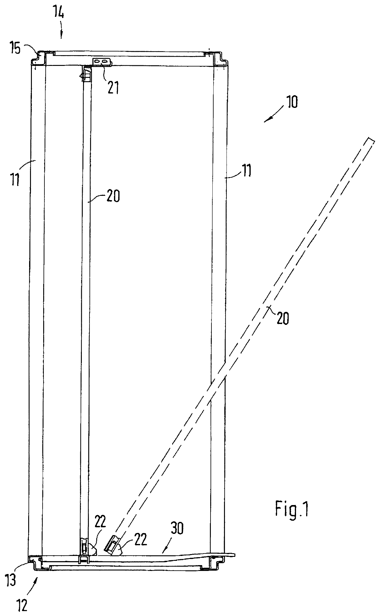
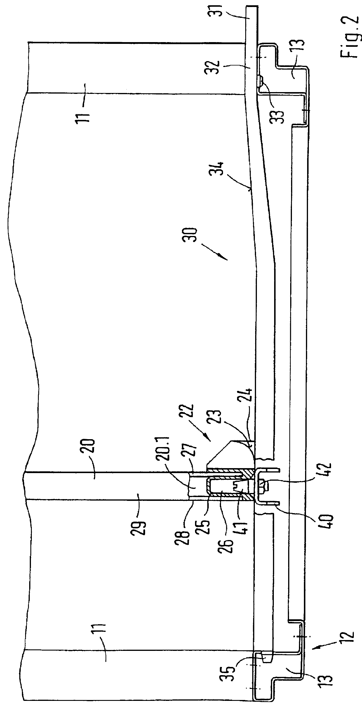
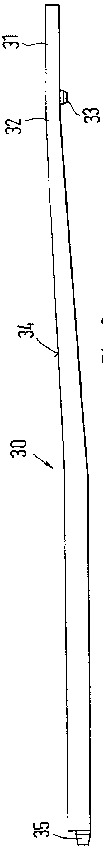
FIG. 1 shows a rack 10 of a switchgear cabinet. The rack 10 is assembled from vertical and horizontal frame legs 11, 13 and 15. The horizontal frame legs 13, 15 respectively form a closed bottom or cover frame 12, or respectively 14. An assembly plate 20 can be inserted into the interior of the switchgear cabinet. In the present example, the assembly plate 20 is pushed into the interior space formed by the rack 10 through the open front of the switchgear cabinet. The front of the switchgear cabinet can be closed by means of a cabinet door, which is not shown in FIG. 1, for reasons of clarity. Guide rails 30 are used for inserting the assembly plate 20 into the switchgear cabinet. Viewed from the front of the switchgear cabinet, the guide rails 30 are inserted into the left and right lower lateral areas of the bottom frame 12. Sliders 22, which are connected with the assembly plate 20, can be displaced on the guide rails 30. In the mounted position, the assembly plate 20 extends vert...


PUM


Abstract

PCT No. PCT/EP97/06145 Sec. 371 Date May 17, 1999 Sec. 102(e) Date May 17, 1999 PCT Filed Nov. 6, 1997 PCT Pub. No. WO98/23138 PCT Pub. Date May 28, 1998A switching cabinet which is enclosed by wall elements and a door. An assembly plate is placed parallel to a vertical side wall. The assembly plate can be moved in a direction of the associated side wall by sliders on at least one guide rail and brought into a position for mounting. Limited mounting opportunities, because of the guide rails, are thus avoided by designing the guide rails as a separate part, by providing positioning units which are detachably secured to the switching cabinet, and by being able to remove the guide rails from the cabinet after the assembly plate is positioned.

Description

1. Field of the InventionThis invention relates to a switchgear cabinet, which can be closed by wall elements and a cabinet door, wherein an assembly plate is arranged parallel with a vertical lateral wall, and which can be displaced on at least one guide rail in the direction toward the associated lateral wall using sliders and can be brought into a mounting position.2. Description of Prior ArtSuch a switchgear cabinet is known, for example, from German Patent Reference DE 41 40 072 A1. Such switchgear cabinets have a rack which is assembled from vertical and horizontal frame legs. The two lower horizontal frame legs, which extend in the direction of the depth of the switchgear cabinet, are formed by a multi-beveled sheet metal blank. In the open hollow profile produced in this manner, a strip with a longitudinal edge is created, on which the slider is placed with a slit-shaped receiver. Thus the assembly plate can be displaced on its sliders in the direction toward the lateral wal...

Claims


Application Information

Patent Timeline
Patent Type & Authority Patents(United States)
IPC IPC(8): H02B1/32H02B1/00H02B1/30H05K7/18H02B1/36
CPCH02B1/32
Inventor REUTER, WOLFGANGROOT, PAUL
Owner RITTALWERK RUDOLF LOH GMBH & CO KG
Why Eureka
Try Eureka