Method and apparatus for multi-beam optical scanning capable of effectively adjusting a scanning line pitch

a multi-beam optical scanning and scanning line technology, applied in the direction of inking apparatus, instruments, optical elements, etc., can solve the problems of cumbersome accumulation of mounting positions, failure to form a desired shape, and deviation of the dot positional in the sub-scanning direction

Inactive Publication Date: 2005-01-04
RICOH KK
View PDF7 Cites 55 Cited by
  • Summary
  • Abstract
  • Description
  • Claims
  • Application Information

AI Technical Summary

Benefits of technology

The technical effect of this patent is that it describes a new way to make sure that images are clear and have good color accuracy when they're printed or displayed on screens. This method uses special technology called Optical Scanning Apparatus (OSA) that creates many small laser beams with precise spacing between them. These beams help ensure consistent quality across all parts of the image.

Problems solved by technology

The technical problem addressed in this patent text is the deviation of dot position in the sub-scanning direction caused by the bending of optical devices in the optical scanning system of a color image forming apparatus. This can result in a deformation of the scanning lines and lead to color deviation in the image quality. The patent proposes a solution to improve the quality of color images created by a full color copying machine by accurately adjusting the scanning lines of multiple laser light beams for the respective color images to the same position.

Method used


Image

  • Method and apparatus for multi-beam optical scanning capable of effectively adjusting a scanning line pitch
  • Method and apparatus for multi-beam optical scanning capable of effectively adjusting a scanning line pitch
  • Method and apparatus for multi-beam optical scanning capable of effectively adjusting a scanning line pitch

Examples


Embodiment Construction

In describing preferred embodiments illustrated in the drawings, specific terminology is employed for the sake of clarity. However, the disclosure of this patent specification is not intended to be limited to the specific terminology so selected and it is to be understood that each specific element includes all technical equivalents that operate in a similar manner.

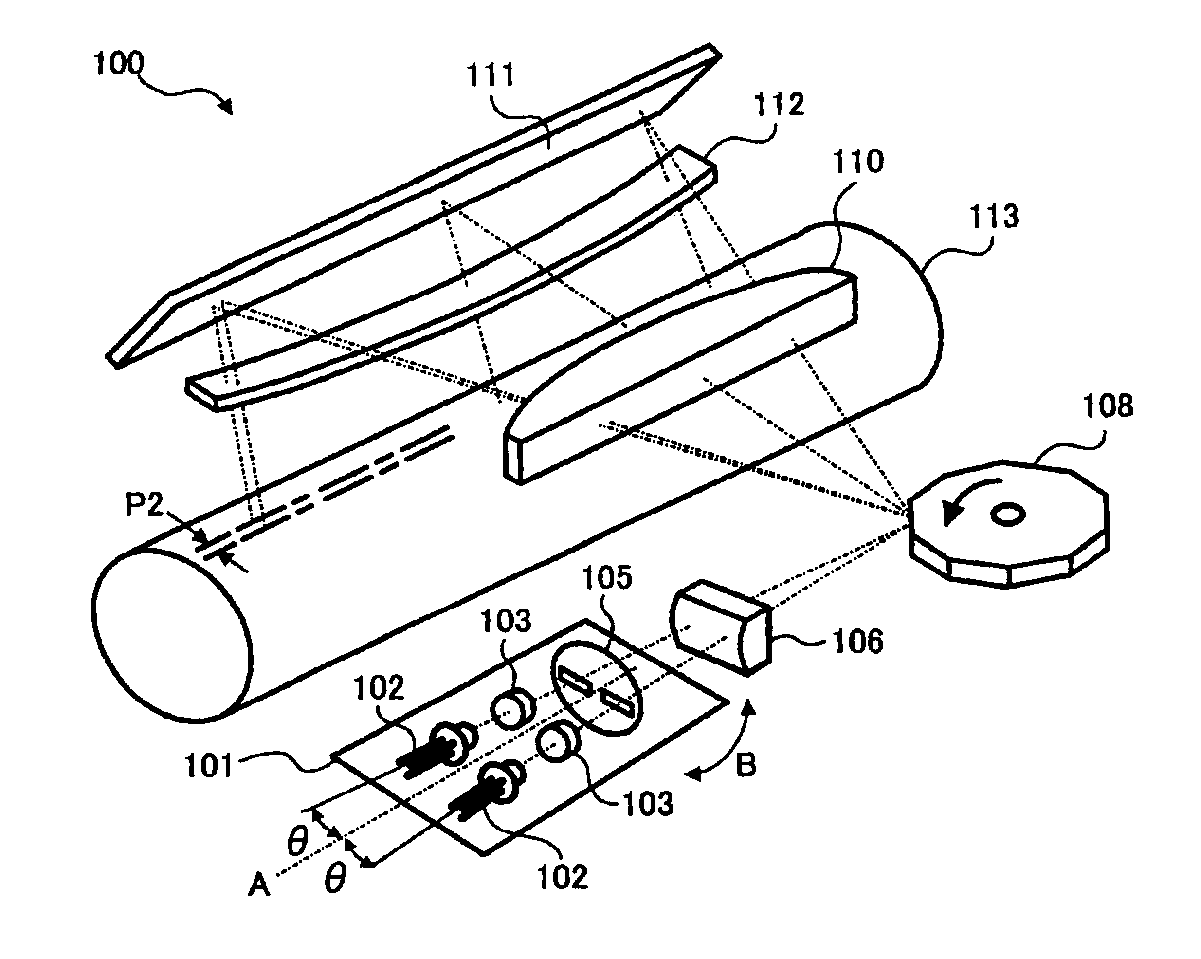
Referring now to the drawings, wherein like reference numerals designate identical or corresponding parts throughout the several views, particularly as to FIGS. 5-7, a description is made of a multi-beam optical scanning apparatus 100 according to a preferred embodiment of the present invention. As shown in FIG. 5, the multi-beam optical scanning apparatus 100 is provided with a laser light source unit 101 that includes two light sources 102 (e.g., laser diodes) and a corresponding pair of coupling lenses 103 and an aperture element 105 having two slits. The multi-beam optical scanning apparatus 100 further includes a cyl...


PUM


Abstract

An optical scanning apparatus includes light sources, an aperture having, and coupling lenses. Numbers of the light sources and the coupling lenses are equal to each other and the apparatus satisfies an inequality 12.7 <(D×β0×m0×xdpi)/(2×NA) <38.1 and an equation β0=(β+−β)/(n−1), wherein D represents a width of the slit of the aperture, β0represents a beam open angle, mo represents a total lateral magnification ratio, dpi represents a number of dots per inch, NA represents a numerical aperture, β+ represents a positive open angle, β represents a negative open angle, and n represents the number. Further, an image forming apparatus using this optical scanning apparatus and an image forming method are provided.

Description


Claims


Application Information

Patent Timeline
Owner RICOH KK
Why Eureka
Try Eureka