Golf club head with high center of gravity

a golf club and high center of gravity technology, applied in the field of golf clubs, can solve problems such as poor performance, and achieve the effect of sufficient backspin and smooth contour

Active Publication Date: 2005-09-06
KARSTEN MFG CORP
View PDF16 Cites 284 Cited by
  • Summary
  • Abstract
  • Description
  • Claims
  • Application Information

AI Technical Summary

Benefits of technology

[0004]The present invention comprises a golf club head formed of a hollow metal body having a center of gravity that is above the geometric center of the club face. According to a preferred embodiment of the present invention, the hollow metal body of the club head has a sole plate that is smoothly contoured and devoid of any inefficient structures such as weight pads or other mass concentrations. By avoiding the use of inefficient structures such as weight pads, more material is available for the structural walls of the club head body while maintaining the club head within acceptable weight limitations. Moreover, placement of the center of gravity above the center line of the face ensures that sufficient backspin will be imparted to the golf ball when struck by the club.

Problems solved by technology

Moreover, as the club head volume increases, the moment of inertia of the club heads also increase, leading to poor performance if prior art methods of locating the center of gravity below the center of the club face are followed.

Method used


Image

  • Golf club head with high center of gravity
  • Golf club head with high center of gravity
  • Golf club head with high center of gravity

Examples


Embodiment Construction

[0011]The drawing figures are intended to illustrate the general manner of construction and are not necessarily to scale. In the detailed description and in the drawing figures, specific illustrative examples are shown and herein described in detail. It should be understood, however, that the drawing figures and the detailed description are not intended to limit the invention to the particular form disclosed but are merely illustrative and intended to teach one of ordinary skill how to make and / or use the invention claimed herein and for setting forth the best mode for carrying out the invention.

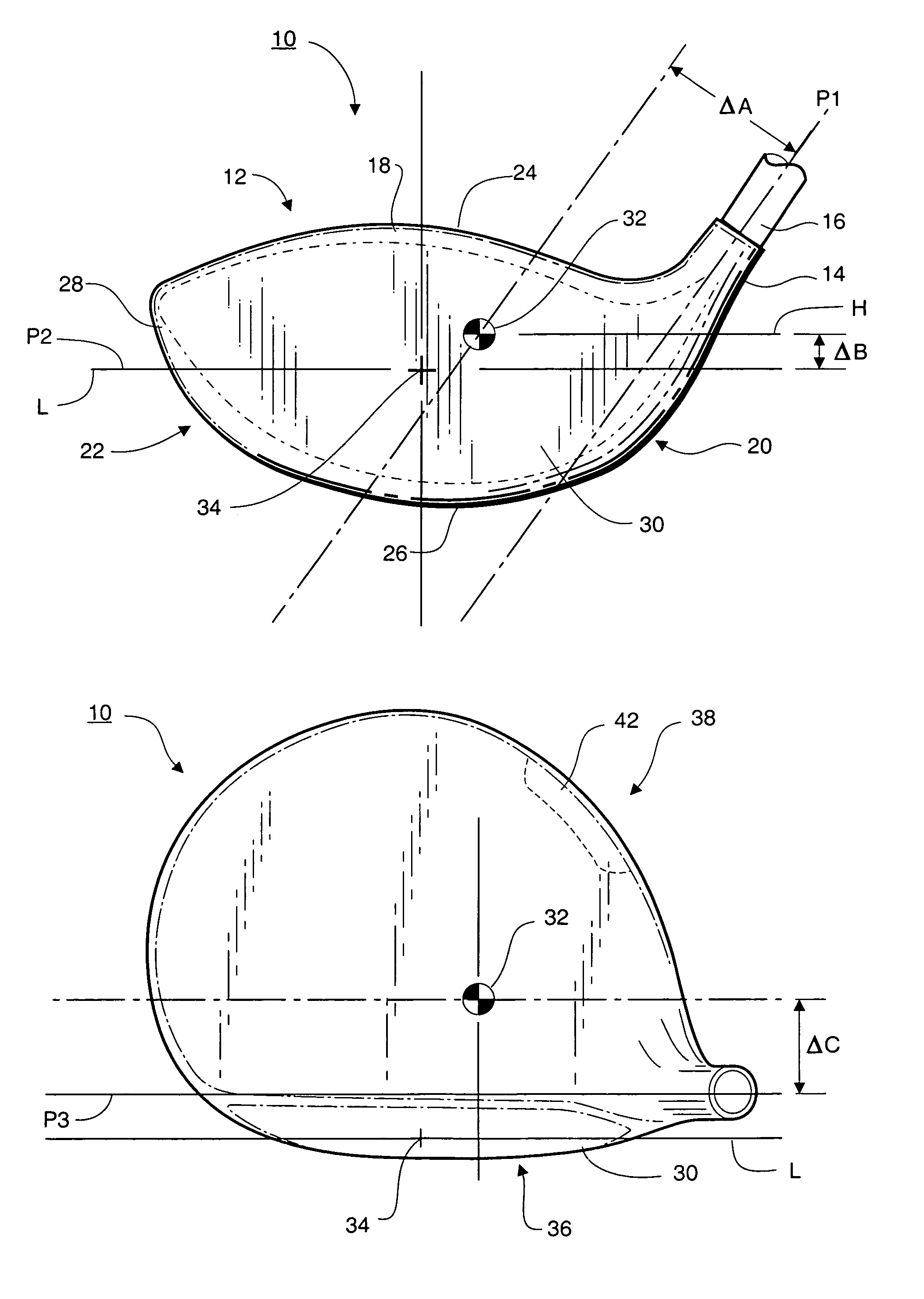
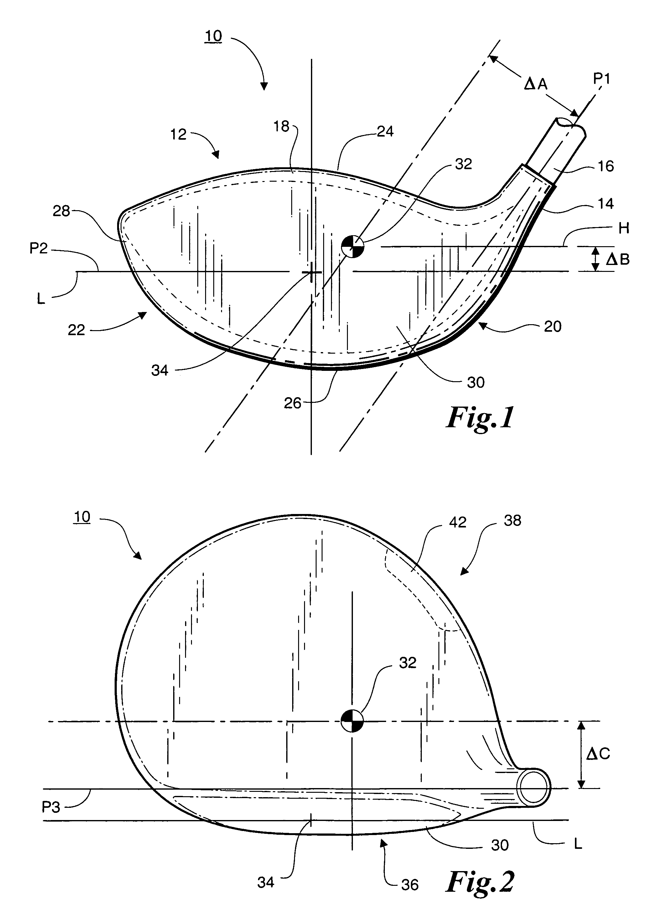
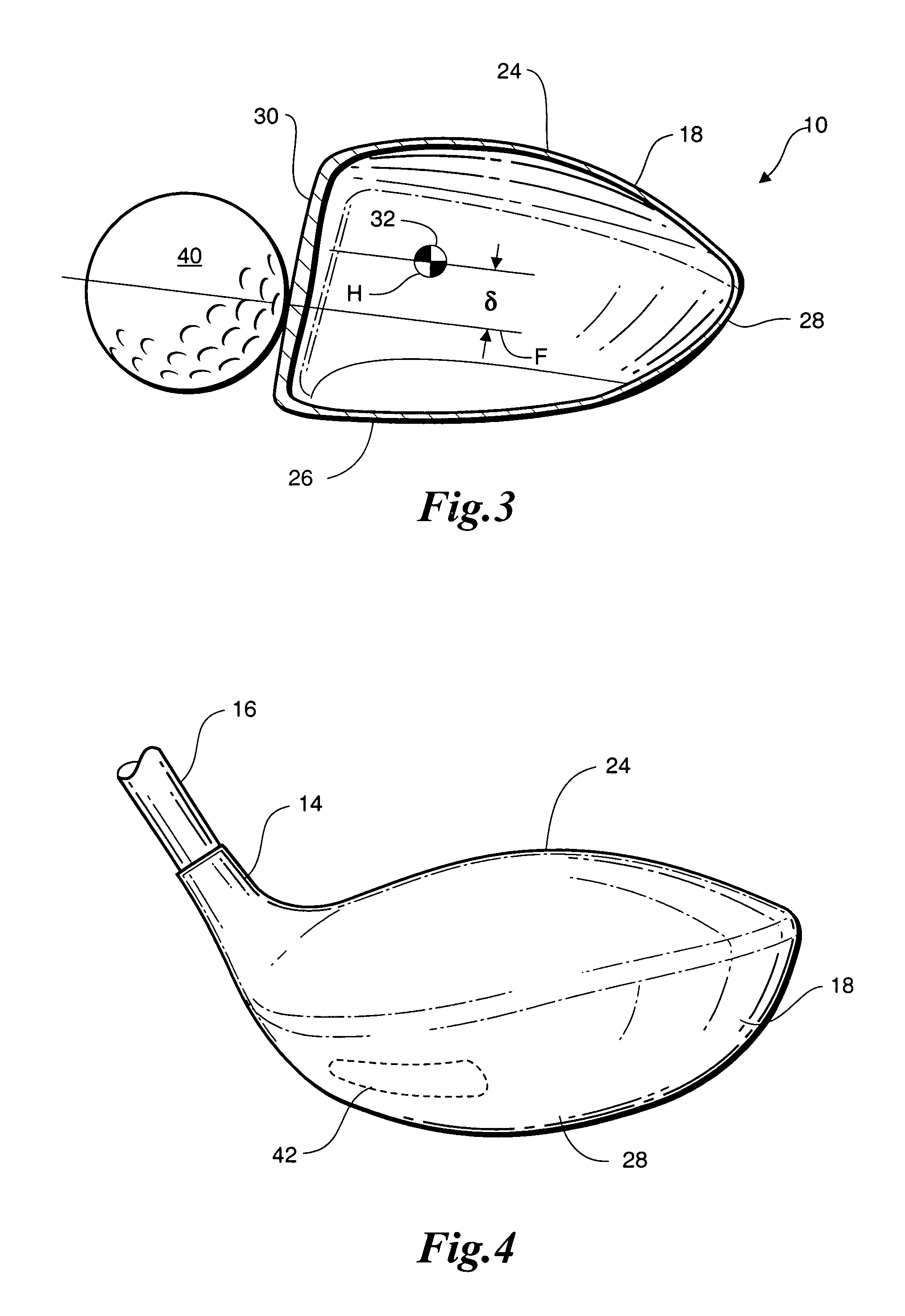
[0012]Referring to FIG. 1, golf club 10 includes a head 12, a hosel 14 and shaft 16. Head 12 includes a hollow body 18 having a heel end 20 and a toe end 22. Hollow body 18 is formed as a shell composed of a crown 24, a sole 26 and a skirt 28 connecting the crown and the sole together. Hollow body 18 may be assembled from a series of forged pieces, but in the illustrative embodiment, compris...


PUM


Abstract

A golf club head is formed of a hollow metal body having a center of gravity that is above the geometric center of the club face. The hollow metal body of the club head has a sole plate that is smoothly contoured and devoid of any inefficient structures such as weight pads or other mass concentrations. By avoiding the use of inefficient structures such as weight pads, more material is available for the structural walls of the club head body while maintaining the club head within acceptable weight limitations. Moreover, placement of the center of gravity above the center line of the face ensures that sufficient backspin will be imparted to the golf ball when struck by the club.

Description

BACKGROUND OF THE INVENTION[0001]This invention relates generally to golf clubs and, in particular, to so-called metal wood drivers.[0002]Recent developments in golf club design have included improvements in drivers, which are clubs used primarily to strike a golf ball resting on a golf tee. These improvements have resulted in drivers with club heads consisting of a hollow shell usually made of metal, such as steel, aluminum, or titanium. These hollow shells typically have a weight pad located on the sole of the club for the purpose of moving the center of gravity downward toward the sole and inward toward the heel of the club head. One example of a golf club head consisting of a hollow metal shell with a weight pad is disclosed in U.S. Pat. No. 5,851,160 to Rugge, et al. According to Rugge, et al., moving the center of gravity to a position below the center of the impact face reduces the amount of backspin imparted to the golf ball by creating a counteracting torque couple between ...

Claims


Application Information

Patent Timeline
Patent Type & Authority Patents(United States)
IPC IPC(8): A63B53/02A63B53/04A63B59/00
CPCA63B53/0466A63B59/0074A63B2053/0462A63B2053/0458A63B2053/0408A63B2053/0416A63B60/02A63B60/42A63B53/0408A63B53/0416A63B53/0458A63B53/0462
Inventor SCHWEIGERT, BRADLEY D.SERRANO, ANTHONY D.
Owner KARSTEN MFG CORP
Why Eureka
Try Eureka